Conceptual Design of the Wide-Body PIS-413 WING LOAD AND TWR ESTIMATION 4 Wing Load and TWR Estimation 4.1 Landing Stage Based on the experience value and the aircraft performance,the landing distance is chosen as 1600 m,also expressed as 5413.38 ft. The relationship of the approach speed and the landing distance can be shown in the following equation,in which the distance is in the unit 'ft'and the speed in the 'kn': S=0.3V2 (4.1) Then the result of the approach speed is given by: 5413.38f =134.33kn (4.2) 0.3 Actually,there is an experience equation connecting the landing distance and the wing load that can expressed as below: S=5 +S (4.3) S八Cmx In this equation,the parameter Sa is chosen as 305 m for civil aircrafts. Considering the wide range of China's territory and the future improvement,the parameter o equals to 0.7.The lift coefficient can be chosen as 3.0. Thus,the allowed maximum wing load at the landing stage can be calculated: S-S×oC,=564.9kg/m2 5 (4.4) 4.2 Stall Speed Another way to calculate the wing load can start from the stall speed. For civil aircrafts,the minimum approach speed is 1.3 times of the stall speed that the approximate stall speed can be obtained based on the following equation: 匕=V-134,33km=103.33kn=103.33x1852 m/s=53.16m/s (4.5) 1.3 1.3 3600 6
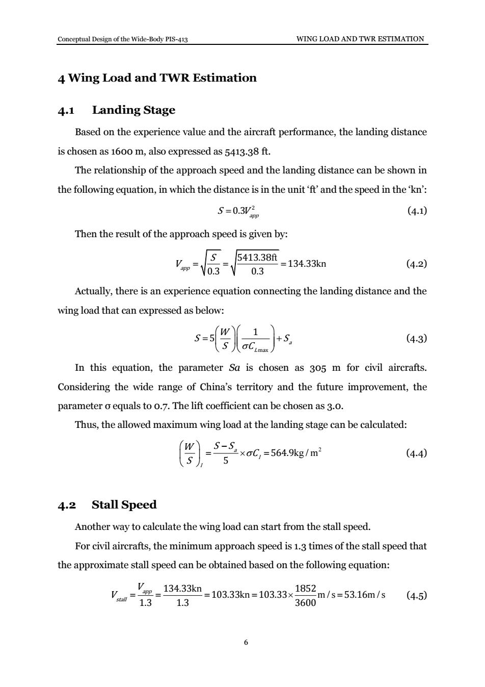
Conceptual Design of the Wide-Body PIS-413 WING LOAD AND TWR ESTIMATION 6 4 Wing Load and TWR Estimation 4.1 Landing Stage Based on the experience value and the aircraft performance, the landing distance is chosen as 1600 m, also expressed as 5413.38 ft. The relationship of the approach speed and the landing distance can be shown in the following equation, in which the distance is in the unit ‘ft’ and the speed in the ‘kn’: 2 0.3 app S V (4.1) Then the result of the approach speed is given by: ft kn 5413.38 134.33 0.3 0.3 app S V (4.2) Actually, there is an experience equation connecting the landing distance and the wing load that can expressed as below: max 1 5 a L W S S S C (4.3) In this equation, the parameter Sa is chosen as 305 m for civil aircrafts. Considering the wide range of China’s territory and the future improvement, the parameter σ equals to 0.7. The lift coefficient can be chosen as 3.0. Thus, the allowed maximum wing load at the landing stage can be calculated: 2 kg / m 564.9 5 a l l W S S C S (4.4) 4.2 Stall Speed Another way to calculate the wing load can start from the stall speed. For civil aircrafts, the minimum approach speed is 1.3 times of the stall speed that the approximate stall speed can be obtained based on the following equation: kn kn m / s m / s 134.33 1852 103.33 103.33 53.16 1.3 1.3 3600 app stall V V (4.5)

Conceptual Design of the Wide-Body PIS-413 WING LOAD AND TWR ESTIMATION The wing load then can be estimated using the below equation while choosing the standard air density to be 1.225 kg/m3 and the maximum lift coefficient to be 3.25: yW,C-克x125x5316×325=562548g1m2 W 1 (4.6) However,the result is clearly beyond the reasonable range of the wing load which should not be taken into consideration. 4.3 Cruise Stage For the maximization of the flight range,the principles of choosing the wing load should be started from the maximization of the lift-to-drag ratio during the cruise stage. For turbojet aircrafts,when the zero lift drag is three times of the induced drag,the flight range can reach the biggest value.Therefore,the corresponding wing load can be shown in the below equation. (4.7) In this equation,the parameter g equals to 9.8.For turbojet aircrafts,the zero lift drag coefficient can be chosen as 0.015.The Oswald efficiency coefficient e reflecting the level of drags is chosen to be 0.46.The parameter A represents the wing area that can be initially chosen to be 9.8.The parameter Q known as the dynamic pressure can only be obtained after the calculation of the cruise speed.The cruise height equals to 38000 ft,which is also 11582.4 m.The air density can be calculated using the parameter of cruise height: H-11000 p=0.3639e643162=0.3324kg/m3 (4.8) The air temperature,the sound speed and the cruise speed can be expressed and calculated using the equations: T=T-6×h(km)=288-6×11.582=218.51K (4.9) a=VyRT=V1.4×287×218.51=296.30m/s (4.10) Vm=Ma×a=0.78x296.30=231.11m/s (4.11) 7
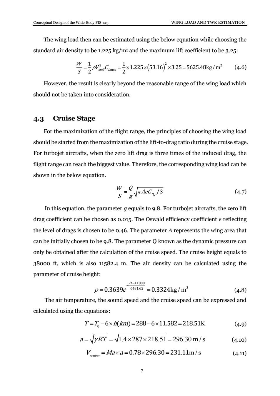
Conceptual Design of the Wide-Body PIS-413 WING LOAD AND TWR ESTIMATION 7 The wing load then can be estimated using the below equation while choosing the standard air density to be 1.225 kg/m3 and the maximum lift coefficient to be 3.25: 2 kg / m 2 2 max 1 1 1.225 53.16 3.25 5625.48 2 2 stall L W V C S (4.6) However, the result is clearly beyond the reasonable range of the wing load which should not be taken into consideration. 4.3 Cruise Stage For the maximization of the flight range, the principles of choosing the wing load should be started from the maximization of the lift-to-drag ratio during the cruise stage. For turbojet aircrafts, when the zero lift drag is three times of the induced drag, the flight range can reach the biggest value. Therefore, the corresponding wing load can be shown in the below equation. 0 / 3 D W Q AeC S g (4.7) In this equation, the parameter g equals to 9.8. For turbojet aircrafts, the zero lift drag coefficient can be chosen as 0.015. The Oswald efficiency coefficient e reflecting the level of drags is chosen to be 0.46. The parameter A represents the wing area that can be initially chosen to be 9.8. The parameter Q known as the dynamic pressure can only be obtained after the calculation of the cruise speed. The cruise height equals to 38000 ft, which is also 11582.4 m. The air density can be calculated using the parameter of cruise height: 3 kg / m 11000 6431.62 0.3639 0.3324 H e (4.8) The air temperature, the sound speed and the cruise speed can be expressed and calculated using the equations: T T h km 0 6 ( ) 288 6 11.582 218.51K (4.9) a RT 1.4 287 218.51 296.30 m / s (4.10) 0.78 296.30 231.11m / s cruise V Ma a (4.11)

Conceptual Design of the Wide-Body PIS-413 WING LOAD AND TWR ESTIMATION With the above data,the dynamic pressure Q can be easily obtained: Q-p9-克0324×2311f-8705N/s (4.12) Further calculation concerning the wing load can then be finished with the result of241.04kg/m3. The thrust weight ratio at the cruise stage can be estimated using the Raymer equation in which for civil aircrafts a=0.267,C=0.363,Mamax =0.84: T W =aMa6x=0.267×0.840363=0.251 (4.13) 4.4 Takeoff Stage Based on the earlier estimation and calculation,the transformation from the wing load at landing stage to the take-off stage has to use the weight coefficient between these two stages.As Wi=78.39%Wiake-off,the wing load at the take-off stage can then be obtained: 0.7839=564.9/0.7839=720.63kg/m2 (4.14) Same as the above transformation,the wing load at the take-off stage from that of the cruise stage can be based on the weight coefficient.As We =98%Wiake-off,the wing load at the take-off stage can be calculated: 0.98=241.04/0.7839=245.96kg/m2 (4.15) take-off,1 4.5 5 Requirements of Maximum Ceiling For the turbojet aircrafts, (4.16) 8
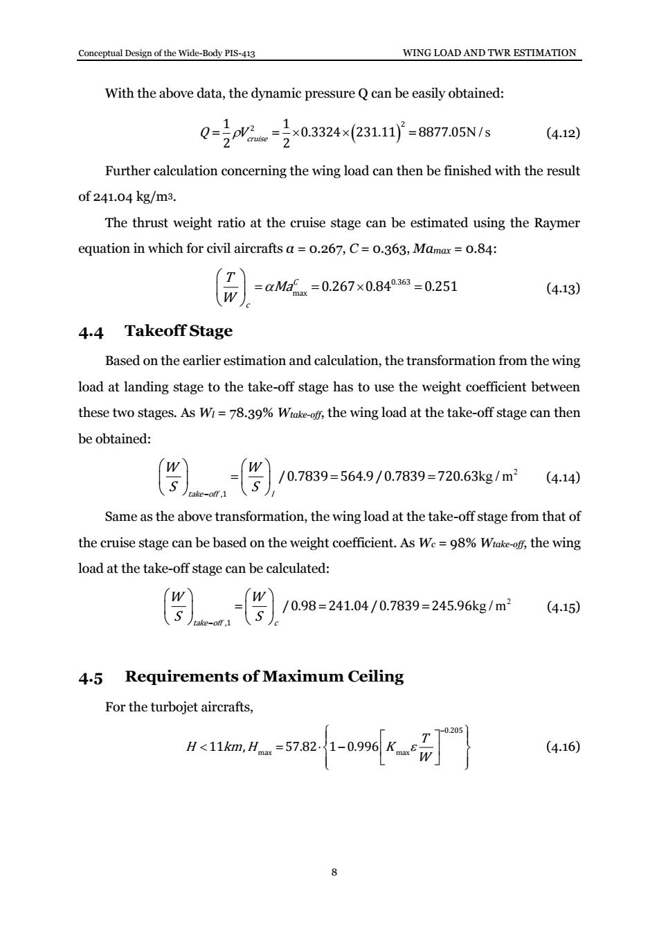
Conceptual Design of the Wide-Body PIS-413 WING LOAD AND TWR ESTIMATION 8 With the above data, the dynamic pressure Q can be easily obtained: N / s 2 1 1 2 0.3324 231.11 8877.05 2 2 Q Vcruise (4.12) Further calculation concerning the wing load can then be finished with the result of 241.04 kg/m3. The thrust weight ratio at the cruise stage can be estimated using the Raymer equation in which for civil aircrafts α = 0.267, C = 0.363, Mamax = 0.84: 0.363 max 0.267 0.84 0.251 C c T Ma W (4.13) 4.4 Takeoff Stage Based on the earlier estimation and calculation, the transformation from the wing load at landing stage to the take-off stage has to use the weight coefficient between these two stages. As Wl = 78.39% Wtake-off, the wing load at the take-off stage can then be obtained: 2 kg / m ,1 /0.7839 564.9/0.7839 720.63 take off l W W S S (4.14) Same as the above transformation, the wing load at the take-off stage from that of the cruise stage can be based on the weight coefficient. As Wc = 98% Wtake-off, the wing load at the take-off stage can be calculated: 2 kg / m ,1 /0.98 241.04/0.7839 245.96 take off c W W S S (4.15) 4.5 Requirements of Maximum Ceiling For the turbojet aircrafts, 0.205 max max 11 , 57.82 1 0.996 T H km H K W (4.16)

Conceptual Design of the Wide-Body PIS-413 WING LOAD AND TWR ESTIMATION H>11km,H=57821-0.965 (4.17) In the above equations,Kmax=15.The parameter concerning the engine speed performance can be calculated using the equation s=1-0.32/+0.40M2-0.01/3.As M=0.78,the parameter equals to o.9890. To sum up,the value of the thrust weight ratio is o.1984. 4.6 Requirements of Maximum Level Speed For the turbojet aircrafts, H>11km,V=15.94(T/W)(W/S)E/C (4.18) In this equation,Cpequals to 0.05 and the maximum level speed Vmax=248.89 m/s =896.004 km/h that should be expressed in the unit 'km/h'.Therefore,the following relationship between the wing load and the thrust weight ratio can be gained: (T/W))(W/S)=159.74 (4.19) From the earlier calculated results of the take-off wing load,the final value can be chosen as 610 kg/m2.Then,the thrust weight ratio is o.2619. 4.7 Final Decision Based on the above analysis,the final wing load is chosen to be 610 kg/m2.And the minimum value of the thrust weight ratio should be o.2619,the final result is chosen as 0.32 concerning the enlarged sizes in the future. 9
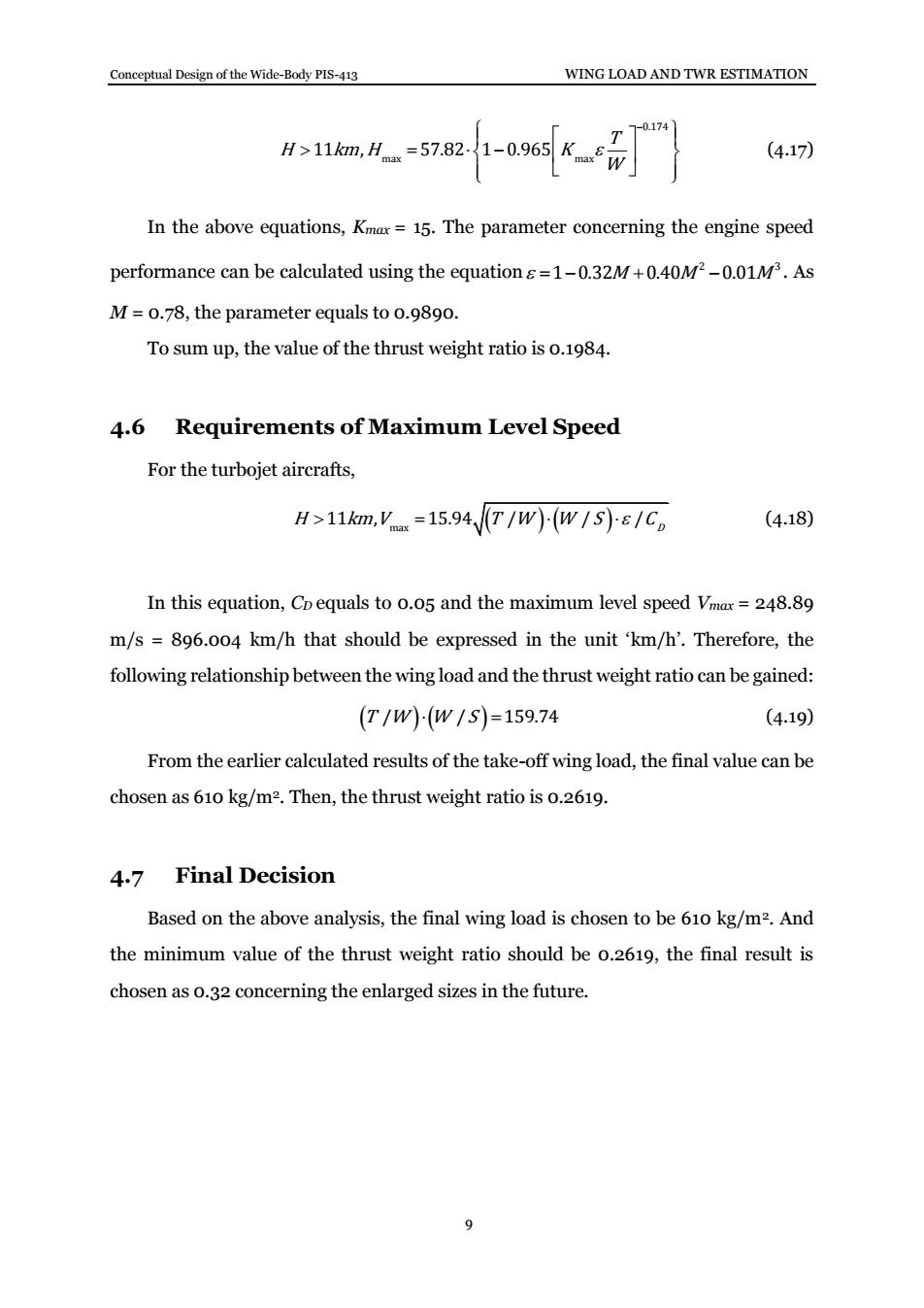
Conceptual Design of the Wide-Body PIS-413 WING LOAD AND TWR ESTIMATION 9 0.174 max max 11 , 57.82 1 0.965 T H km H K W (4.17) In the above equations, Kmax = 15. The parameter concerning the engine speed performance can be calculated using the equation 2 3 1 0.32 0.40 0.01 M M M . As M = 0.78, the parameter equals to 0.9890. To sum up, the value of the thrust weight ratio is 0.1984. 4.6 Requirements of Maximum Level Speed For the turbojet aircrafts, max 11 , 15.94 / / / H km V T W W S C D (4.18) In this equation, CD equals to 0.05 and the maximum level speed Vmax = 248.89 m/s = 896.004 km/h that should be expressed in the unit ‘km/h’. Therefore, the following relationship between the wing load and the thrust weight ratio can be gained: T W W S / / 159.74 (4.19) From the earlier calculated results of the take-off wing load, the final value can be chosen as 610 kg/m2. Then, the thrust weight ratio is 0.2619. 4.7 Final Decision Based on the above analysis, the final wing load is chosen to be 610 kg/m2. And the minimum value of the thrust weight ratio should be 0.2619, the final result is chosen as 0.32 concerning the enlarged sizes in the future

Conceptual Design of the Wide-Body PIS-413 FUSELAGE DESIGN 5 Fuselage Design 5.1 Introduction and Considerations Fuselage is the main load part of the aircraft.For civil aircraft,fuselage has two main functions:One is to accommodate the crew,passengers,cargos and equipment, the other is to connect the other parts,including wings,tail,landing gear,engine,etc. In the design process of fuselage,the following primary principals should be taken into consideration: (1)Number of passengers (2)Low aerodynamic drag (3)Minimum structural weight (4)Passenger comfort and cabin layout flexibility (5)Dynamic structural stability and further stretch(fitness ratio) (6)Structural support for wing and tail forces,and accommodation for undercarriage (7)Ease of cargo handling (8)Noise,climate control,galleys,APU,etc. (9)Certification requirement(emergency exits,oxygen system,etc.) 5.2 Main Parameters In the design of PIS-413,the maximum number of passengers is 400,and the specific seat distribution is as follows. Table 6.Seat Distribution. Class Total seats Business Economy Mixed type 390 30 360 Economy 400 0 400 10
Conceptual Design of the Wide-Body PIS-413 FUSELAGE DESIGN 10 5 Fuselage Design 5.1 Introduction and Considerations Fuselage is the main load part of the aircraft. For civil aircraft, fuselage has two main functions:One is to accommodate the crew, passengers, cargos and equipment, the other is to connect the other parts, including wings, tail, landing gear, engine, etc. In the design process of fuselage, the following primary principals should be taken into consideration: (1) Number of passengers (2) Low aerodynamic drag (3) Minimum structural weight (4) Passenger comfort and cabin layout flexibility (5) Dynamic structural stability and further stretch (fitness ratio) (6) Structural support for wing and tail forces, and accommodation for undercarriage (7) Ease of cargo handling (8) Noise, climate control, galleys, APU, etc. (9) Certification requirement (emergency exits, oxygen system, etc.) 5.2 Main Parameters In the design of PIS-413, the maximum number of passengers is 400, and the specific seat distribution is as follows. Table 6. Seat Distribution. Class Total seats Business Economy Mixed type 390 30 360 Economy 400 0 400