●●● ●●●● ●●●●● ●●●0 Applying v()to() ●●●●0 ●●●0 ●●●● ●● e)-R+ee-e y=a+jB=(R+j@L)(G+j@C) Characteristic impedance: R+joL R+joL 特性阻抗 Y \G+j@C Relation of the voltage and current on the line: 线上电压和电流的关系 =Z= 6 11
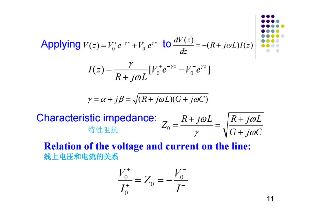
Relation of the voltage and current on the line: 线上电压和电流的关系 Applying to Characteristic impedance: 特性阻抗 11 0 0 ( ) z z Vz Ve Ve ( ) ( )() dV z R j LI z dz 0 0 () [ ] z z Iz Ve Ve R jL 0 R jL R jL Z G jC 0 0 0 0 V V Z I I j R jLG jC ( )( )
●●● ●●●● ●●●● I()= Characteristic impedance ●●●● ●●●● Z。 Zo Impedance ●.●●● Time domain solution of wave equation: 波动方程的时域解 v(z,t)=Vo cos(@t-Bz+")e+Vo cos(ot+Bz+)ea= Waveguide wavelength:the distance between two successive points of equal phase波导波长 0t-Bz1+p=ot-Bz2+φ++2π 2π → g= B 0t=Bz-中+C The phase velocity the speed at which a constant phase point Vp= dz⊙ dt B =九gj travels down相速度 12
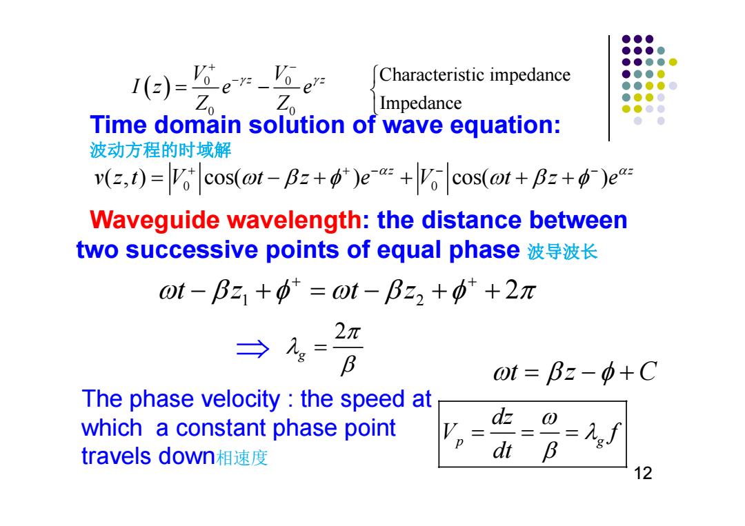
Waveguide wavelength: the distance between two successive points of equal phase 波导波长 Time domain solution of wave equation: 波动方程的时域解 tz C The phase velocity : the speed at which a constant phase point travels down相速度 12 0 0 0 0 V V z z Iz e e Z Z Characteristic impedance Impedance 0 0 ( , ) cos( ) cos( ) z z vzt V t z e V t z e 1 2 tz tz 2 2 g p g dz V f dt
●●● ●●●● 3,Lossless of Transmission Lines ●●●●● ●●●0 ●●●●0 ●●●0 R+joL ●●●● =+G+c setting R=G=0 y=(R+joL)(G+j@C)=j@VLC=a+jB c=0 → R+joL 2元 2π 0 Z0= VG+j@C Bo√LCf√LC Vp= B LC V(=)=Vo'ein+e 1(2)= Z Z。 13
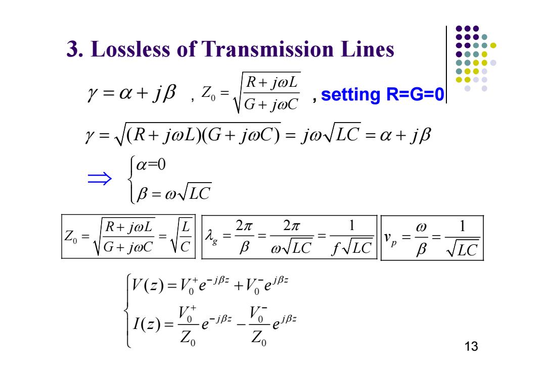
3. Lossless of Transmission Lines , , setting R=G=0 13 j 0 R j L Z G jC ( )( ) R j L G j C j LC j =0 L C 0 R j L L Z G j C C 22 1 g L C f LC 1 p v L C 0 0 0 0 0 0 ( ) ( ) j z jz j z jz Vz Ve Ve V V I ze e Z Z
●● ●●●● To conclude-1 ●●●● ●●●● ●●●● ●Definition of“Microwave and RF Design of ●●●0 ●●●色 Vireless Systems” ● ● Microwave;RF;Wireless;Systems. Major wireless system in use today PCS,WLAN,GPS,DBS,LMDS,RFID,MMDS,Bluetooth ●System performance Frequency and Power,Maximum data rate,Operating range, Power requirement,Bit error rate .. ●System design Propagation,Fading,Noise,Modulation method, Intermodulation,I/O interface,Bit error rate,System scheme Circuits design Filter,Amplifier,Mixer,Oscillator,Phase-looked loop, Modulator/Demodulator,Antenna 14
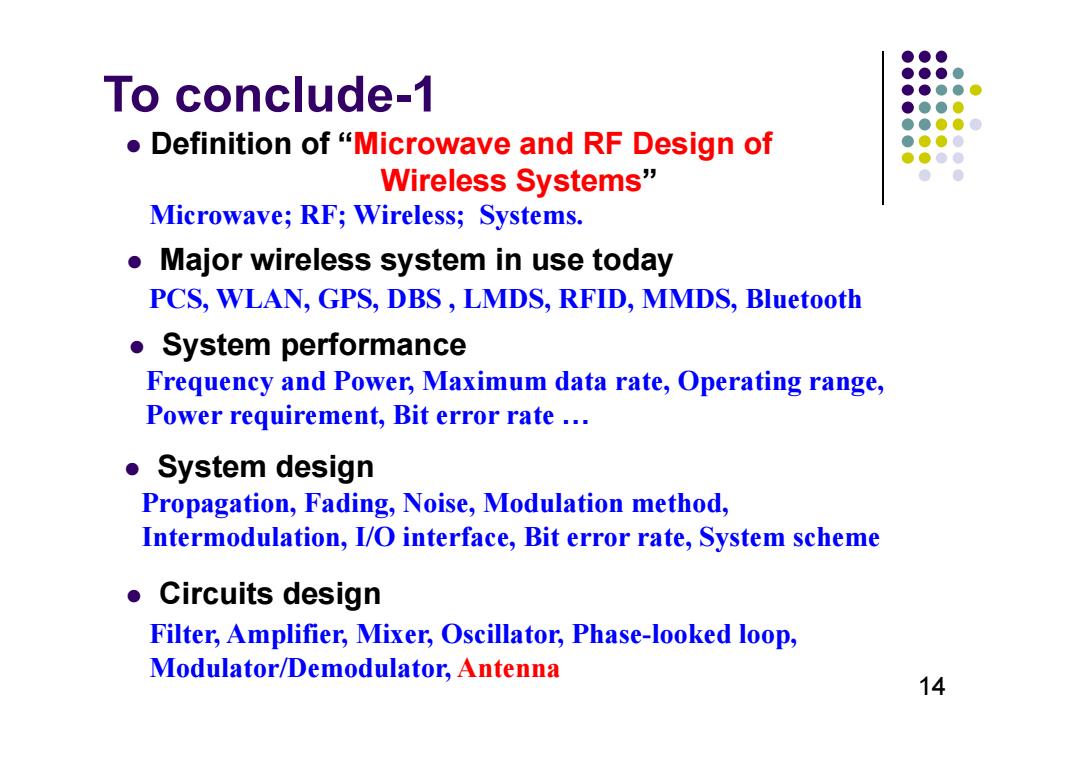
To conclude-1 PCS, WLAN, GPS, DBS , LMDS, RFID, MMDS, Bluetooth Microwave; RF; Wireless; Systems. Frequency and Power, Maximum data rate, Operating range, Power requirement, Bit error rate … Propagation, Fading, Noise, Modulation method, Intermodulation, I/O interface, Bit error rate, System scheme Filter, Amplifier, Mixer, Oscillator, Phase-looked loop, Modulator/Demodulator, Antenna Definition of “Microwave and RF Design of Wireless Systems” Major wireless system in use today System performance System design Circuits design 14
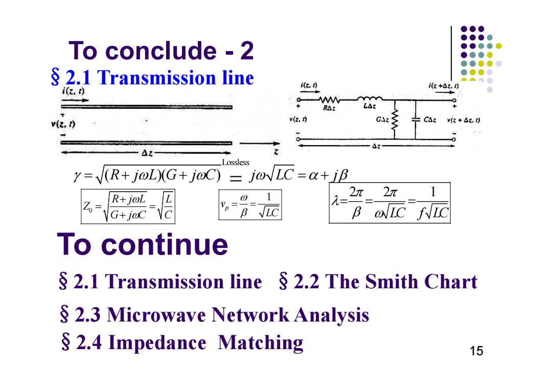
●●● ●●●● To conclude -2 ●●●●● ●●●● ●●●●0 2.1 Transmission line ●●●● z,) i(z+Az.) i(z,) 0 R△t v(2.0 v(, GA CAz v(z +Az.t) Lossless y=(R+j@L)(G+j@C)=j@LC=a+jB 分、 R+joL 1 2n 2n 1 G+j@C B IC fIC To continue §2.1 Transmission line§2.2 The Smith Chart 2.3 Microwave Network Analysis 2.4 Impedance Matching 15
To conclude - 2 §2.1 Transmission line 15 Lossless ( )( ) R j L G j C j LC j 0 R jL L Z G jC C 22 1 LC f LC 1 p v LC §2.4 Impedance Matching §2.3 Microwave Network Analysis §2.1 Transmission line §2.2 The Smith Chart To continue