floorplan and Cost((B))be the predefined cost metric.The cost metric can be the area of the minimum bounding rectangle (MBR)of FB),the wirelength,or a linear combination of the area and the wirelength.Area minimization is one of the key objectives.Because the purpose of this paper is a"proof of concept",we limit the Cost function to the area.Other elements will be included in the cost function in future studies. The shape and orientation of each block are fixed before applying the MBS.Because our idea of the MBS originates from the observation that a floorplan can be obtained by moving blocks on the chip according to some rules,designing rules for moves becomes the key task. In the following text,the bottom and left sides of the chip are fixed to form the X-and Y-axis, respectively.Each block is first placed on an initial position from where it can move to other places at the first quadrant.The initial positions are defined as follows: Definition 1:Let (widthg.and heightg denote the coordinate of the left-bottom corner,the width,and the height of the MBR of B,respectively.Let Box denote the MBR of the blocks that have been placed and (denote the coordinate of the right-top corner of Box.The coordinate of the left-bottom corner of Box is always(0,0).Thus, there are four initial positions for B,namely, initial position0:(xg,y哈)←(O,ya") initial position 1(x哈,yg)←(xar,0) (1) initial position 2: (始,哈)←((max(0,xar-width)),Jyor) initial position3(xg,y哈)←(xar,max(0,yar-height)) where max(a,b)denotes the larger one between a and b. According to Definition 1,the four initial positions for a new block are determined by the MBR of the blocks that have been placed and are illustrated in Fig.1(a).There are two special 11
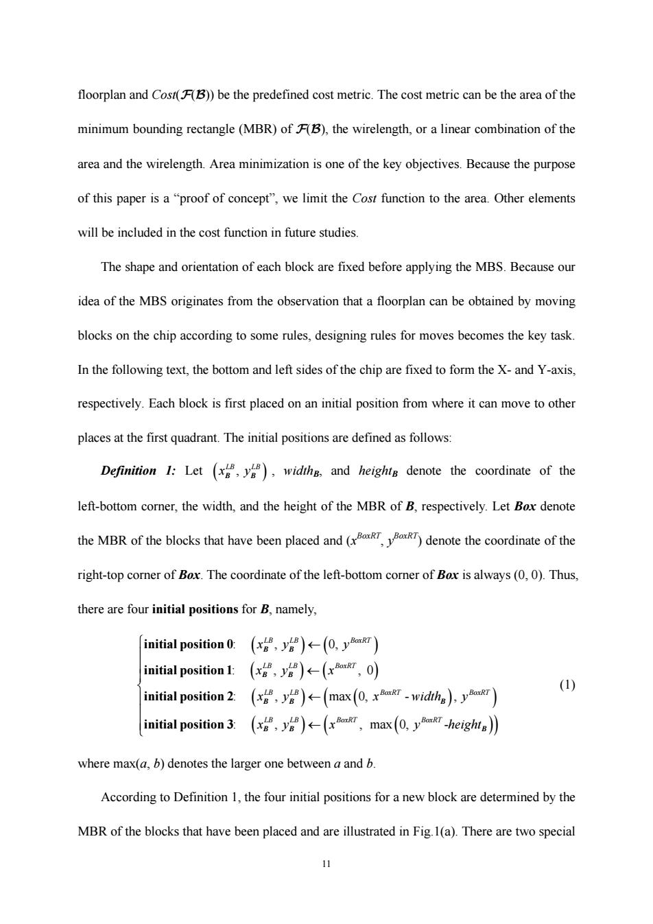
11 floorplan and Cost(F(B)) be the predefined cost metric. The cost metric can be the area of the minimum bounding rectangle (MBR) of F(B), the wirelength, or a linear combination of the area and the wirelength. Area minimization is one of the key objectives. Because the purpose of this paper is a “proof of concept”, we limit the Cost function to the area. Other elements will be included in the cost function in future studies. The shape and orientation of each block are fixed before applying the MBS. Because our idea of the MBS originates from the observation that a floorplan can be obtained by moving blocks on the chip according to some rules, designing rules for moves becomes the key task. In the following text, the bottom and left sides of the chip are fixed to form the X- and Y-axis, respectively. Each block is first placed on an initial position from where it can move to other places at the first quadrant. The initial positions are defined as follows: Definition 1: Let ( ) , LB LB x y B B , widthB, and heightB denote the coordinate of the left-bottom corner, the width, and the height of the MBR of B, respectively. Let Box denote the MBR of the blocks that have been placed and (x BoxRT, y BoxRT) denote the coordinate of the right-top corner of Box. The coordinate of the left-bottom corner of Box is always (0, 0). Thus, there are four initial positions for B, namely, ( ) ( ) ( )( ) () ( ) ( ) ( ) : , 0, : , , 0 : , max 0, - , : , , max 0, LB LB BoxRT LB LB BoxRT LB LB BoxRT BoxRT LB LB BoxRT BoxR xy y xy x x y x width y xy x y ← ← ← ← initial position 0 initial position 1 initial position 2 initial position 3 B B B B BB B B B ( ) ( ) - T height ⎧ ⎪ ⎪ ⎪ ⎨ ⎪ ⎪ ⎪ ⎩ B (1) where max(a, b) denotes the larger one between a and b. According to Definition 1, the four initial positions for a new block are determined by the MBR of the blocks that have been placed and are illustrated in Fig.1(a). There are two special
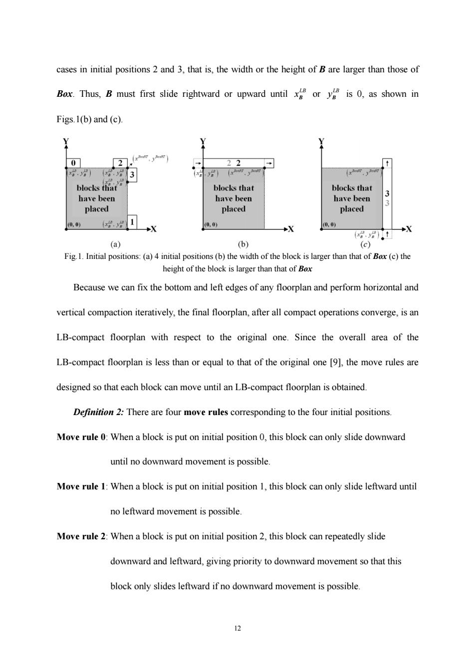
cases in initial positions 2 and 3,that is,the width or the height of B are larger than those of Box.Thus,B must first slide rightward or upward until ory is 0,as shown in Figs.1(b)and(c). 0 22 blocks that blocks that blocks that have been have been have been 3 placed placed placed (0,0 L◆X 0,0) 0,0) X (分分)。t (a) (b) (c) Fig.1.Initial positions:(a)4 initial positions(b)the width of the block is larger than that of Box(c)the height of the block is larger than that of Box Because we can fix the bottom and left edges of any floorplan and perform horizontal and vertical compaction iteratively,the final floorplan,after all compact operations converge,is an LB-compact floorplan with respect to the original one.Since the overall area of the LB-compact floorplan is less than or equal to that of the original one [9],the move rules are designed so that each block can move until an LB-compact floorplan is obtained. Definition 2:There are four move rules corresponding to the four initial positions. Move rule 0:When a block is put on initial position 0,this block can only slide downward until no downward movement is possible. Move rule 1:When a block is put on initial position 1,this block can only slide leftward until no leftward movement is possible Move rule 2:When a block is put on initial position 2,this block can repeatedly slide downward and leftward,giving priority to downward movement so that this block only slides leftward if no downward movement is possible 12
12 cases in initial positions 2 and 3, that is, the width or the height of B are larger than those of Box. Thus, B must first slide rightward or upward until LB xB or LB yB is 0, as shown in Figs.1(b) and (c). Fig.1. Initial positions: (a) 4 initial positions (b) the width of the block is larger than that of Box (c) the height of the block is larger than that of Box Because we can fix the bottom and left edges of any floorplan and perform horizontal and vertical compaction iteratively, the final floorplan, after all compact operations converge, is an LB-compact floorplan with respect to the original one. Since the overall area of the LB-compact floorplan is less than or equal to that of the original one [9], the move rules are designed so that each block can move until an LB-compact floorplan is obtained. Definition 2: There are four move rules corresponding to the four initial positions. Move rule 0: When a block is put on initial position 0, this block can only slide downward until no downward movement is possible. Move rule 1: When a block is put on initial position 1, this block can only slide leftward until no leftward movement is possible. Move rule 2: When a block is put on initial position 2, this block can repeatedly slide downward and leftward, giving priority to downward movement so that this block only slides leftward if no downward movement is possible
Move rule 3:When a block is put on initial position 3,this block can repeatedly slide leftward and downward,giving priority to leftward movement so that this block only slides downward if no leftward movement is possible. Definition 3:A Moving Block Sequence (MBS)has two tuples.One denotes the permutation of all block names,and the other denotes the initial positions (IPs)of all blocks,IP,namely, MBS=(r,IP)and元=(πo,元,,rn-i)and IP=(R,I,,IPn-i) (2) where zi (0<isn-1)denotes a block among {Bo,B1,...B),and IPjE(0,1,2,3)(1sjsn-1) denotes the initial position for 7.zo is placed at the left-bottom corner of the first quadrant and m,,...,are placed at the first quadrant in the order they occur in As can be seen,there are always four choices for initial positions of any type of blocks and no extra constraints are exerted on solution spaces.Such a kind of solution space is suitable for designing effective crossover operators.Thus,the MBS is useful for EAs in solving floorplanning problems. Theorem I:Let MBS be the set of all possible MBSs for n blocks;then,the size of the solution space MBS]is equal to (n!22(D)). Proof:The number of combinations of is n!and that of IP is (4(D).Thus, 1MBS=nl×4m-=nl×22m-l) (3)▣ TV.Algorithm Transforming an MBS to a Floorplan Although rectilinear blocks can be classified into two types,convex rectilinear blocks and concave rectilinear blocks,both boundaries are composed of a set of vertical and horizontal edges,and the distribution of these edges on the four orientations (top,bottom,left,and right) 13
13 Move rule 3: When a block is put on initial position 3, this block can repeatedly slide leftward and downward, giving priority to leftward movement so that this block only slides downward if no leftward movement is possible. Definition 3: A Moving Block Sequence (MBS) has two tuples. One denotes the permutation of all block names, π, and the other denotes the initial positions (IPs) of all blocks, IP, namely, MBS IP IP = = () ( ) π π= , and , , ..., and , , ..., ππ π 01 1 1 2 1 n n − − (IP IP IP ) (2) where πi (0≤i≤n-1) denotes a block among {B0, B1, …, Bn-1}, and IPj∈{0, 1, 2, 3}(1≤j≤n-1) denotes the initial position for πj. π0 is placed at the left-bottom corner of the first quadrant and π1, π2, …, πn-1 are placed at the first quadrant in the order they occur in π. As can be seen, there are always four choices for initial positions of any type of blocks and no extra constraints are exerted on solution spaces. Such a kind of solution space is suitable for designing effective crossover operators. Thus, the MBS is useful for EAs in solving floorplanning problems. Theorem 1: Let MBS be the set of all possible MBSs for n blocks; then, the size of the solution space |MBS| is equal to (n!22(n-1)). Proof: The number of combinations of π is n! and that of IP is (4(n-1)). Thus, |MBS| = n! × 4(n-1) = n! × 22(n-1) (3) , IV. Algorithm Transforming an MBS to a Floorplan Although rectilinear blocks can be classified into two types, convex rectilinear blocks and concave rectilinear blocks, both boundaries are composed of a set of vertical and horizontal edges, and the distribution of these edges on the four orientations (top, bottom, left, and right)
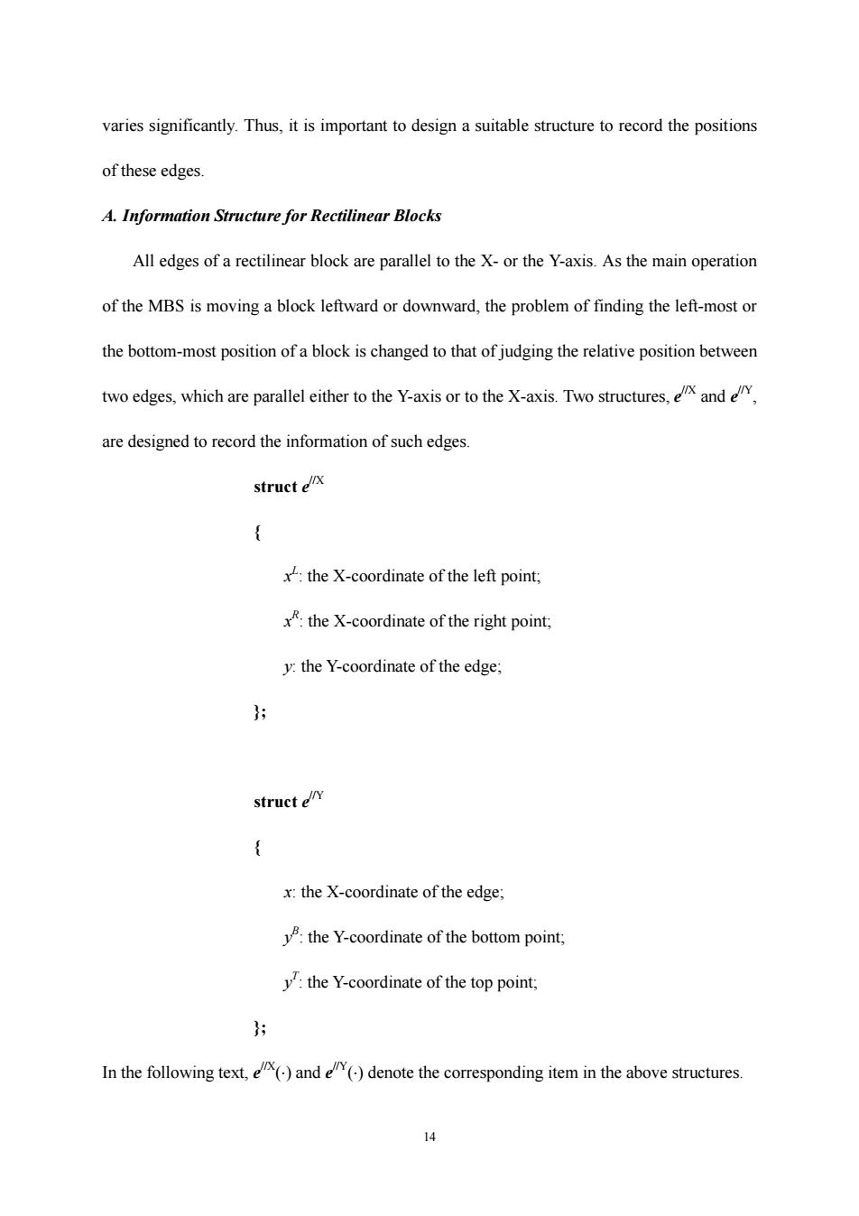
varies significantly.Thus,it is important to design a suitable structure to record the positions of these edges. A.Information Structure for Rectilinear Blocks All edges of a rectilinear block are parallel to the X-or the Y-axis.As the main operation of the MBS is moving a block leftward or downward,the problem of finding the left-most or the bottom-most position of a block is changed to that of judging the relative position between two edges,which are parallel either to the Y-axis or to the X-axis.Two structures,xand are designed to record the information of such edges. struct elx { x the X-coordinate of the left point; x:the X-coordinate of the right point; y:the Y-coordinate of the edge; }好 struct ely { x:the X-coordinate of the edge; the Y-coordinate of the bottom point; y:the Y-coordinate of the top point, }; In the following text,()and ()denote the corresponding item in the above structures. 女
14 varies significantly. Thus, it is important to design a suitable structure to record the positions of these edges. A. Information Structure for Rectilinear Blocks All edges of a rectilinear block are parallel to the X- or the Y-axis. As the main operation of the MBS is moving a block leftward or downward, the problem of finding the left-most or the bottom-most position of a block is changed to that of judging the relative position between two edges, which are parallel either to the Y-axis or to the X-axis. Two structures, e //X and e //Y, are designed to record the information of such edges. struct e//X { x L : the X-coordinate of the left point; x R : the X-coordinate of the right point; y: the Y-coordinate of the edge; }; struct e//Y { x: the X-coordinate of the edge; y B : the Y-coordinate of the bottom point; y T : the Y-coordinate of the top point; }; In the following text, e //X(⋅) and e //Y(⋅) denote the corresponding item in the above structures
The edges of a rectilinear block can be classified into four types. Definition 4:Suppose sliding along the boundary of a rectilinear block clockwise.If the edge slides from right to left,it is a bottom edge;if it slides from left to right,it is a top edge; if it slides from bottom to top,it is a left edge;and if it slides from top to bottom,it is a right edge. The following structure is designed to record the information of a rectilinear block: struct B type:HRiB: BEX:an ordered set recording the bottom edges from bottom to top, TEX:an ordered set recording the top edges from bottom to top; LEY:an ordered set recording the left edges from left to right; REY:an ordered set recording the right edges from left to right. }为 For more clarity,Fig.2 illustrates the four types of edges.As can be seen,a and e are bottom edges;c,i,g,and k are top edges;b,f,d,and j are left edges;h and I are right edges B.Implementation of the Algorithm If a block is projected to the X-axis vertically or to the Y-axis horizontally,the blocks in the projection area will affect the bottom-most or the left-most position where this block can move to.In Fig.3,the shadow area d is the projection area of A.As can be seen,B,C,D,and Fig.2.The edges of a rectilinear block 小
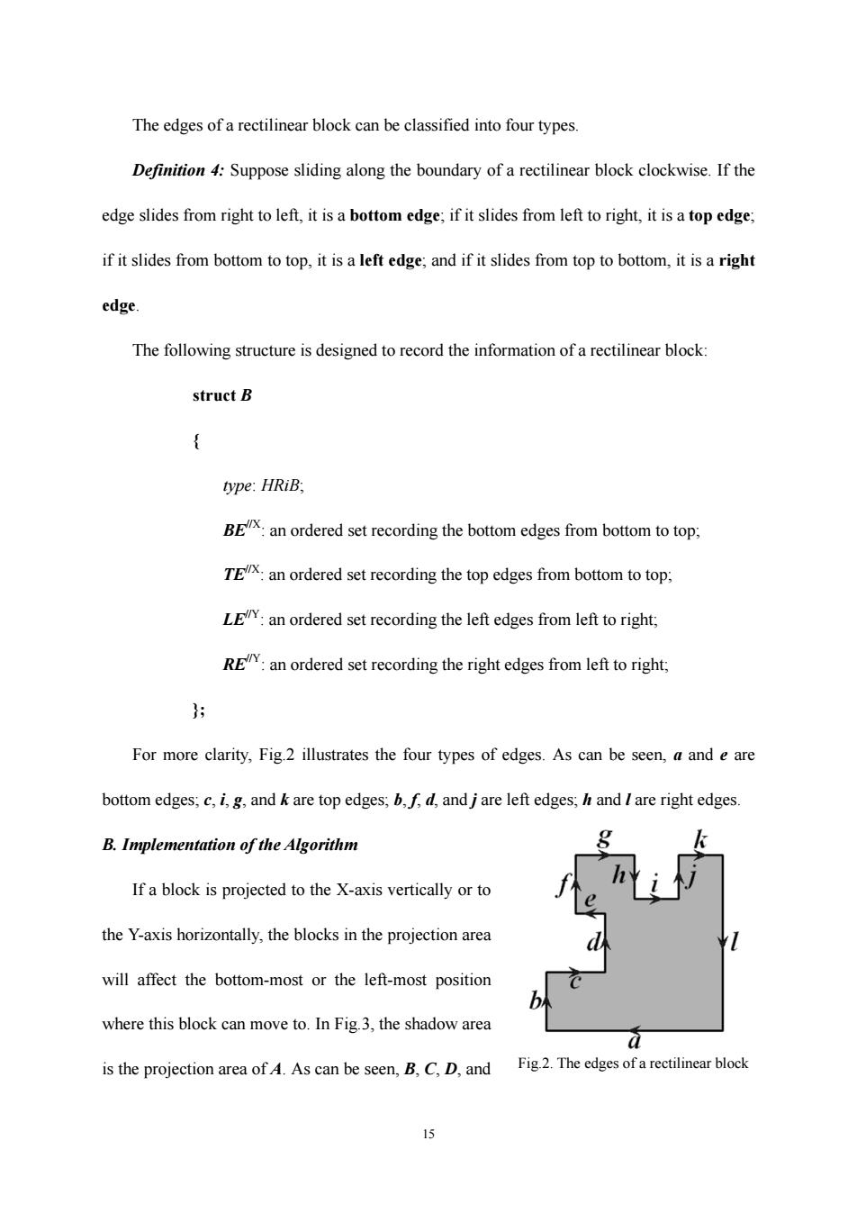
15 The edges of a rectilinear block can be classified into four types. Definition 4: Suppose sliding along the boundary of a rectilinear block clockwise. If the edge slides from right to left, it is a bottom edge; if it slides from left to right, it is a top edge; if it slides from bottom to top, it is a left edge; and if it slides from top to bottom, it is a right edge. The following structure is designed to record the information of a rectilinear block: struct B { type: HRiB; BE//X: an ordered set recording the bottom edges from bottom to top; TE//X: an ordered set recording the top edges from bottom to top; LE//Y: an ordered set recording the left edges from left to right; RE//Y: an ordered set recording the right edges from left to right; }; For more clarity, Fig.2 illustrates the four types of edges. As can be seen, a and e are bottom edges; c, i, g, and k are top edges; b, f, d, and j are left edges; h and l are right edges. B. Implementation of the Algorithm If a block is projected to the X-axis vertically or to the Y-axis horizontally, the blocks in the projection area will affect the bottom-most or the left-most position where this block can move to. In Fig.3, the shadow area is the projection area of A. As can be seen, B, C, D, and Fig.2. The edges of a rectilinear block