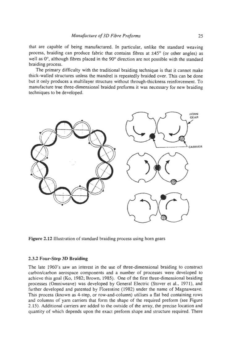
Manufacture of 3D Fibre Preforms 25 that are capable of being manufactured.In particular,unlike the standard weaving process,braiding can produce fabric that contains fibres at t45(or other angles)as well as 0,although fibres placed in the 90 direction are not possible with the standard braiding process. The primary difficulty with the traditional braiding technique is that it cannot make thick-walled structures unless the mandrel is repeatedly braided over.This can be done but it only produces a multilayer structure without through-thickness reinforcement.To manufacture true three-dimensional braided preforms it was necessary for new braiding techniques to be developed. HORN GEAR CARRIER Figure 2.12 Illustration of standard braiding process using horn gears 2.3.2 Four-Step 3D Braiding The late 1960's saw an interest in the use of three-dimensional braiding to construct carbon/carbon aerospace components and a number of processes were developed to achieve this goal (Ko,1982;Brown,1985).One of the first three-dimensional braiding processes (Omniweave)was developed by General Electric (Stover et al..1971).and further developed and patented by Florentine(1982)under the name of Magnaweave. This process (known as 4-step,or row-and-column)utilises a flat bed containing rows and columns of yarn carriers that form the shape of the required preform (see Figure 2.15).Additional carriers are added to the outside of the array,the precise location and quantity of which depends upon the exact preform shape and structure required.There
Manufacture of 30 Fibre Preforms 25 that are capable of being manufactured. In particular, unlike the standard weaving process, braiding can produce fabric that contains fibres at k45O (or other angles) as well as O", although fibres placed in the 90' direction are not possible with the standard braiding process. The primary difficulty with the traditional braiding technique is that it cannot make thick-walled structures unless the mandrel is repeatedly braided over. This can be done but it only produces a multilayer structure without through-thickness reinforcement. TO manufacture true three-dimensional braided preforms it was necessary for new braiding techniques to be developed. Figure 2.12 Illustration of standard braiding process using horn gears 2.3.2 Four-Step 3D Braiding The late 1960's saw an interest in the use of three-dimensional braiding to construct carbodcarbon aerospace components and a number of processes were developed to achieve this goal (KO, 1982; Brown, 1985). One of the first three-dimensional braiding processes (Omniweave) was developed by General Electric (Stover et al., 1971), and further developed and patented by Florentine (1982) under the name of Magnaweave. This process (known as 4-step, or row-and-column) utilises a flat bed containing rows and columns of yarn carriers that form the shape of the required preform (see Figure 2.15). Additional carriers are added to the outside of the array, the precise location and quantity of which depends upon the exact preform shape and structure required. There
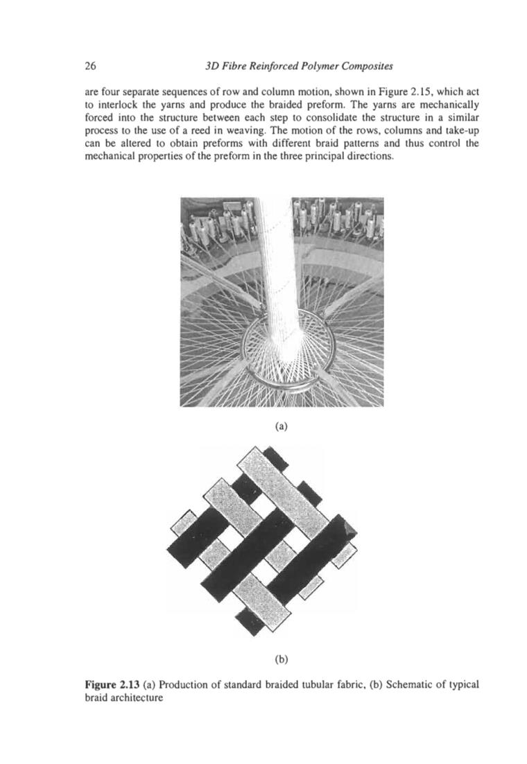
26 3D Fibre Reinforced Polymer Composites are four separate sequences of row and column motion,shown in Figure 2.15,which act to interlock the yarns and produce the braided preform.The yarns are mechanically forced into the structure between each step to consolidate the structure in a similar process to the use of a reed in weaving.The motion of the rows,columns and take-up can be altered to obtain preforms with different braid patterns and thus control the mechanical properties of the preform in the three principal directions. (a) (b) Figure 2.13 (a)Production of standard braided tubular fabric.(b)Schematic of typical braid architecture
26 30 Fibre Reinforced Polymer Composites are four separate sequences of row and column motion, shown in Figure 2.15, which act to interlock the yarns and produce the braided preform. The yarns are mechanically forced into the structure between each step to consolidate the structure in a similar process to the use of a reed in weaving. The motion of the rows, columns and take-up can be altered to obtain preforms with different braid patterns and thus control the mechanical properties of the preform in the three principal directions. Figure 2.13 (a) Production of standard braided tubular fabric, (b) Schematic of typical braid architecture
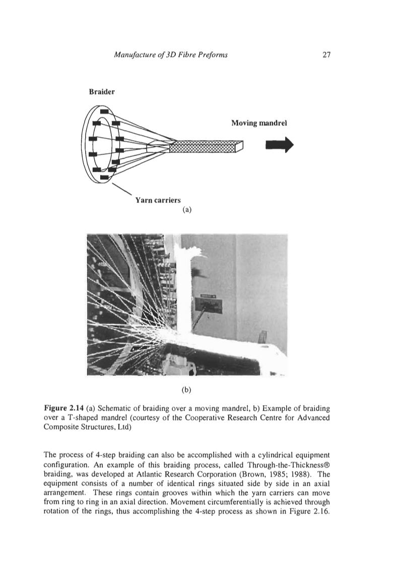
Manufacture of 3D Fibre Preforms 27 Braider Moving mandrel Yarn carriers (a) (b) Figure 2.14 (a)Schematic of braiding over a moving mandrel,b)Example of braiding over a T-shaped mandrel (courtesy of the Cooperative Research Centre for Advanced Composite Structures,Ltd) The process of 4-step braiding can also be accomplished with a cylindrical equipment configuration.An example of this braiding process,called Through-the-Thickness braiding,was developed at Atlantic Research Corporation (Brown,1985;1988).The equipment consists of a number of identical rings situated side by side in an axial arrangement.These rings contain grooves within which the yarn carriers can move from ring to ring in an axial direction.Movement circumferentially is achieved through rotation of the rings,thus accomplishing the 4-step process as shown in Figure 2.16
Manufacture of 30 Fibre Preforms 27 Braider Moving mandrel Yarn carriers (a) Figure 2.14 (a) Schematic of braiding over a moving mandrel, b) Example of braiding over a T-shaped mandrel (courtesy of the Cooperative Research Centre for Advanced Composite Structures, Ltd) The process of 4-step braiding can also be accomplished with a cylindrical equipment configuration. An example of this braiding process, called Through-the-Thickness@ braiding, was developed at Atlantic Research Corporation (Brown, 1985; 1988). The equipment consists of a number of identical rings situated side by side in an axial arrangement. These rings contain grooves within which the yarn carriers can move from ring to ring in an axial direction. Movement circumferentially is achieved through rotation of the rings, thus accomplishing the 4-step process as shown in Figure 2.16
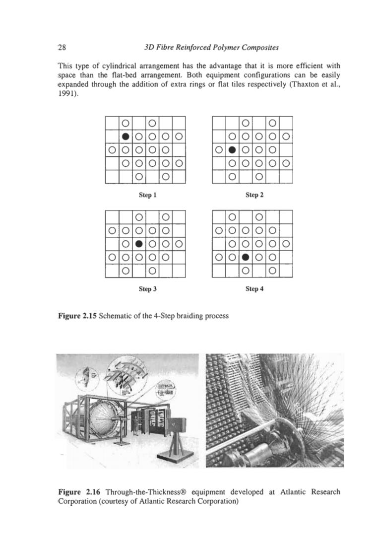
28 3D Fibre Reinforced Polymer Composites This type of cylindrical arrangement has the advantage that it is more efficient with space than the flat-bed arrangement.Both equipment configurations can be easily expanded through the addition of extra rings or flat tiles respectively (Thaxton et al., 1991). ● Step1 Step 2 Step 3 Step4 Figure 2.15 Schematic of the 4-Step braiding process Figure 2.16 Through-the-Thickness equipment developed at Atlantic Research Corporation(courtesy of Atlantic Research Corporation)
28 30 Fibre Reinforced Polymer Composites This type of cylindrical arrangement has the advantage that it is more efficient with space than the flat-bed arrangement. Both equipment configurations can be easily expanded through the addition of extra rings or flat tiles respectively (Thaxton et al., 1991). I I.lolololol lololololol I I!!!!!I * 0.000 Step 1 Step 2 Step 3 Step 4 Figure 2.15 Schematic of the 4-Step braiding process Figure 2.16 Through-the-Thickness8 equipment developed at Atlantic Research Corporation (courtesy of Atlantic Research Corporation)
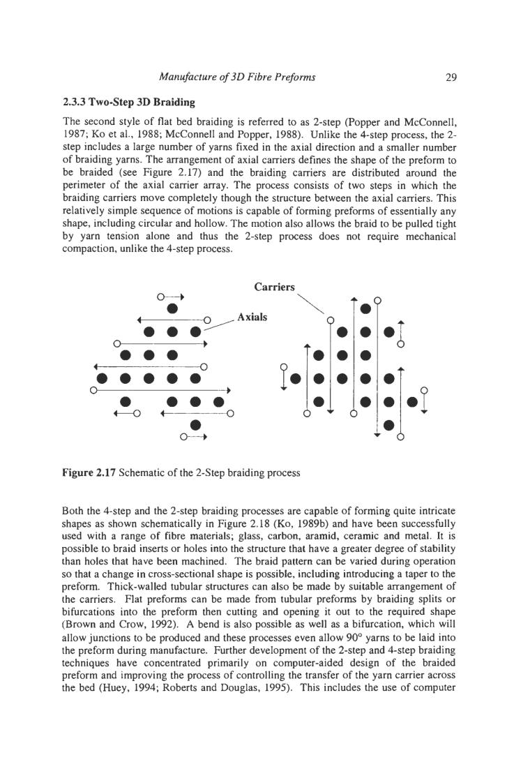
Manufacture of 3D Fibre Preforms 29 2.3.3 Two-Step 3D Braiding The second style of flat bed braiding is referred to as 2-step (Popper and McConnell, 1987;Ko et al.,1988;McConnell and Popper,1988).Unlike the 4-step process,the 2- step includes a large number of yarns fixed in the axial direction and a smaller number of braiding yarns.The arrangement of axial carriers defines the shape of the preform to be braided (see Figure 2.17)and the braiding carriers are distributed around the perimeter of the axial carrier array.The process consists of two steps in which the braiding carriers move completely though the structure between the axial carriers.This relatively simple sequence of motions is capable of forming preforms of essentially any shape,including circular and hollow.The motion also allows the braid to be pulled tight by yarn tension alone and thus the 2-step process does not require mechanical compaction,unlike the 4-step process. Carriers Axials ● Figure 2.17 Schematic of the 2-Step braiding process Both the 4-step and the 2-step braiding processes are capable of forming quite intricate shapes as shown schematically in Figure 2.18(Ko,1989b)and have been successfully used with a range of fibre materials;glass,carbon,aramid,ceramic and metal.It is possible to braid inserts or holes into the structure that have a greater degree of stability than holes that have been machined.The braid pattern can be varied during operation so that a change in cross-sectional shape is possible,including introducing a taper to the preform.Thick-walled tubular structures can also be made by suitable arrangement of the carriers.Flat preforms can be made from tubular preforms by braiding splits or bifurcations into the preform then cutting and opening it out to the required shape (Brown and Crow,1992).A bend is also possible as well as a bifurcation,which will allow junctions to be produced and these processes even allow 90 yarns to be laid into the preform during manufacture.Further development of the 2-step and 4-step braiding techniques have concentrated primarily on computer-aided design of the braided preform and improving the process of controlling the transfer of the yarn carrier across the bed (Huey,1994;Roberts and Douglas,1995).This includes the use of computer
Manufacture of 30 Fibre Preforms 29 2.3.3 Two-step 3D Braiding The second style of flat bed braiding is referred to as 2-step (Popper and McConnell, 1987; KO et al., 1988; McConnell and Popper, 1988). Unlike the 4-step process, the 2- step includes a large number of yarns fixed in the axial direction and a smaller number of braiding yarns. The arrangement of axial carriers defines the shape of the preform to be braided (see Figure 2.17) and the braiding carriers are distributed around the perimeter of the axial carrier array. The process consists of two steps in which the braiding carriers move completely though the structure between the axial carriers. This relatively simple sequence of motions is capable of forming preforms of essentially any shape, including circular and hollow. The motion also allows the braid to be pulled tight by yarn tension alone and thus the 2-step process does not require mechanical compaction, unlike the 4-step process. Carriers v - 000 ..eo. b Po 0 000 f--ot--------o 0 w .Io 0 0 Figure 2.17 Schematic of the 2-Step braiding process Both the 4-step and the 2-step braiding processes are capable of forming quite intricate shapes as shown schematically in Figure 2.18 (KO, 1989b) and have been successfully used with a range of fibre materials; glass, carbon, aramid, ceramic and metal. It is possible to braid inserts or holes into the structure that have a greater degree of stability than holes that have been machined. The braid pattern can be varied during operation so that a change in cross-sectional shape is possible, including introducing a taper to the preform. Thick-walled tubular structures can also be made by suitable arrangement of the carriers. Flat preforms can be made from tubular preforms by braiding splits or bifurcations into the preform then cutting and opening it out to the required shape (Brown and Crow, 1992). A bend is also possible as well as a bifurcation, which will allow junctions to be produced and these processes even allow 90" yarns to be laid into the preform during manufacture. Further development of the 2-step and 4-step braiding techniques have concentrated primarily on computer-aided design of the braided preform and improving the process of controlling the transfer of the yam carrier across the bed (Huey, 1994; Roberts and Douglas, 1995). This includes the use of computer