Manufacture of 3D Fibre Preforms 15 The insertion of the weft yarns can be done using a number of methods.One of the oldest techniques consists of transferring a small package of yarn in a holder(shuttle) through the shed,the yarn being drawn out of the shuttle and laid across the warp yarns as the shuttle moves.This is a relatively slow technique but has the advantage of creating a closed edge to the fabric,as it is a single continuous yarn that is forming the fabric weft.More recent,high-speed techniques involve laying down separate weft yarns across the fabric width.These weft yarns are drawn through the shed mechanically with a long slender arm (rapier)or pushed across with high-pressure bursts of air or water.These processes are faster than shuttle looms,reaching speeds of approximately 600 insertions/minute,but create a loose edge of cut weft yarns that needs to be bound together so that the fabric does not fray (salvage). The final mechanism involved in the weaving process is a comb-like device(reed) that is used to correctly space the warp yarns across the width of the fabric and to compact the fabric after the weft yarns have been inserted.Generally a series of positively driven rollers are used to pull the fabric out of the loom as it is being produced and to provide a level of fabric tension during the weaving process.It should be noted that the resultant fabric consists only of 0 and 90 yarns,conventional weaving is incapable of producing fabrics with yarns at any other angles and this is one of the main disadvantages of weaving over other textile processes. Current,commercial looms generally produce fabric of widths between 1.8-2.5 metres at production rates of metres/minute.The standard weaving process is therefore ideally suited to the cost-effective production of large volumes of material.However, using essentially the same equipment,the process described above can also be used to produce more complex,multilayer fabrics that have yarns in the thickness direction linking the layers together. 2.2.2 Multilayer or 3D Weaving The first major difference between conventional weaving and multilayer weaving is the requirement to have multiple layers of warp yarns.The greater the number of layers required (and thus the thickness of the preform)or the wider the fabric produced,means a larger number of individual warp yarns that have to be fed into the loom and controlled during the lifting sequence.Therefore the source of the warp yarn for multilayer weaving is generally from large creels in which each warp yarn comes from its own individual yarn package.Multiple warp beam systems have also been used although this is not as common.This requirement for a large number of warp ends raises the first disadvantage of weaving,namely that the cost of obtaining (generally) thousands of yarns packages and the time required to set up the large number of warp ends within the loom can be extremely expensive.This non-recurring cost becomes less significant as the length of the fabric being woven increases but having to weave large volumes of the same material restricts the flexibility of the process.Most multilayer weaving is therefore currently used to produce relatively narrow width products,where the number of warp ends is relatively small,or high value products where the cost of the preform production is acceptable. As most 3D composites are produced from high performance yarns (carbon,glass. ceramic,etc)standard textile tensioning rollers are unsuitable and tension control on the individual yarns during the weaving is critical in obtaining a consistent preform quality. This is generally accomplished through spring-loaded or frictional tension devices on
Manufacture of 30 Fibre Preforms 15 The insertion of the weft yarns can be done using a number of methods. One of the oldest techniques consists of transferring a small package of yarn in a holder (shuttle) through the shed, the yarn being drawn out of the shuttle and laid across the warp yarns as the shuttle moves. This is a relatively slow technique but has the advantage of creating a closed edge to the fabric, as it is a single continuous yam that is forming the fabric weft. More recent, high-speed techniques involve laying down separate weft yarns across the fabric width. These weft yams are drawn through the shed mechanically with a long slender arm (rapier) or pushed across with high-pressure bursts of air or water. These processes are faster than shuttle looms, reaching speeds of approximately 600 insertions/minute, but create a loose edge of cut weft yarns that needs to be bound together so that the fabric does not fray (salvage). The final mechanism involved in the weaving process is a comb-like device (reed) that is used to correctly space the warp yarns across the width of the fabric and to compact the fabric after the weft yarns have been inserted. Generally a series of positively driven rollers are used to pull the fabric out of the loom as it is being produced and to provide a level of fabric tension during the weaving process. It should be noted that the resultant fabric consists only of 0" and 90" yams, conventional weaving is incapable of producing fabrics with yarns at any other angles and this is one of the main disadvantages of weaving over other textile processes. Current, commercial looms generally produce fabric of widths between 1.8 - 2.5 metres at production rates of metredminute. The standard weaving process is therefore ideally suited to the cost-effective production of large volumes of material. However, using essentially the same equipment, the process described above can also be used to produce more complex, multilayer fabrics that have yarns in the thickness direction linking the layers together. 2.2.2 Multilayer or 3D Weaving The first major difference between conventional weaving and multilayer weaving is the requirement to have multiple layers of warp yams. The greater the number of layers required (and thus the thickness of the preform) or the wider the fabric produced, means a larger number of individual warp yams that have to be fed into the loom and controlled during the lifting sequence. Therefore the source of the warp yarn for multilayer weaving is generally from large creels in which each warp yarn comes from its own individual yam package. Multiple warp beam systems have also been used although this is not as common. This requirement for a large number of warp ends raises the first disadvantage of weaving, namely that the cost of obtaining (generally) thousands of yarns packages and the time required to set up the large number of warp ends within the loom can be extremely expensive. This non-recurring cost becomes less significant as the length of the fabric being woven increases but having to weave large volumes of the same material restricts the flexibility of the process. Most multilayer weaving is therefore currently used to produce relatively narrow width products, where the number of warp ends is relatively small, or high value products where the cost of the preform production is acceptable. As most 3D composites are produced from high performance yarns (carbon, glass, ceramic, etc) standard textile tensioning rollers are unsuitable and tension control on the individual yarns during the weaving is critical in obtaining a consistent preform quality. This is generally accomplished through spring-loaded or frictional tension devices on

16 3D Fibre Reinforced Polymer Composites the creel or through hanging small weights on the yarns before entering the lifting device.Figure 2.3 illustrates the use of multiple warp beams and hanging weights in multilayer weaving.The lifting mechanisms are the same as used in conventional weaving although the heddle eyes through which the yarn passes tend to be smoothed and rounded to minimise friction with the more brittle high performance fibres. Jacquard lifting mechanisms tend to be used more frequently as their greater control over individual warp yarns offers more flexibility in the weave patterns produced.The weft insertion is accomplished with standard technology (generally a rapier mechanism) inserting individual wefts between the selected warp layers.Variations in the lifting and weft insertion mechanisms to allow multiple sheds to be formed and thus multiple simultaneous weft insertions have also been developed and would allow a faster preform production rate.This type of technology is often regarded as the true 3D weaving. Figure 2.3 Multilayer weaving loom(courtesy of the Cooperative Research Centre for Advanced Composite Structures,Ltd) It is through the design of the lifting pattern that the three-dimensional nature of the weave architecture is produced in multilayer weaving.Commonly the bulk of the warp and weft yarns are designed to lay straight within the preform and thus maximise the mechanical performance.In order to bind the preform together,selected warp yarns, coming from a separate beam if warp beams are used,are lifted and dropped so that their path travels in the thickness direction thus binding the layers together(Figure 2.4)
16 30 Fibre Reinforced Polymer Composites the creel or through hanging small weights on the yarns before entering the lifting device. Figure 2.3 illustrates the use of multiple warp beams and hanging weights in multilayer weaving. The lifting mechanisms are the same as used in conventional weaving although the heddle eyes through which the yarn passes tend to be smoothed and rounded to minimise friction with the more brittle high performance fibres. Jacquard lifting mechanisms tend to be used more frequently as their greater control over individual warp yarns offers more flexibility in the weave patterns produced. The weft insertion is accomplished with standard technology (generally a rapier mechanism) inserting individual wefts between the selected warp layers. Variations in the lifting and weft insertion mechanisms to allow multiple sheds to be formed and thus multiple simultaneous weft insertions have also been developed and would allow a faster preform production rate. This type of technology is often regarded as the true 3D weaving. Figure 2.3 Multilayer weaving loom (courtesy of the Cooperative Research Centre for Advanced Composite Structures, Ltd) It is through the design of the lifting pattern that the three-dimensional nature of the weave architecture is produced in multilayer weaving. Commonly the bulk of the warp and weft yarns are designed to lay straight within the preform and thus maximise the mechanical performance. In order to bind the preform together, selected warp yarns, coming from a separate beam if warp beams are used, are lifted and dropped so that their path travels in the thickness direction thus binding the layers together (Figure 2.4)

Manufacture of 3D Fibre Preforms 17 Such a multilayer weaving loom is described by Yamamoto et al (1995).Examples of such weave architectures that are currently capable of being manufactured using multilayer weaving are illustrated in Figure 2.5.It should be noted that the illustrations in Figure 2.5 show idealised architectures and often these can be very different from the resultant preform architecture (Bannister et al 1998).Tension within and friction between the yarns,together with the initial weave parameters (yarn size and twist,yarn spacing,number of layers,etc)can all affect the final architecture and thus the composite performance.As with conventional weaving,multilayer weaving is only capable of producing fabrics with 0 and 90 in-plane yarns,although the binder yarns can be oriented at an angle.This tends to limit the use of these preforms as their shear and torsional properties can be relatively low.Various 3D weaving techniques can produce preforms with yarns at other angles although this requires the use of highly specialised equipment,which will be discussed later. Figure 2.4 Illustration of multilayer weaving Figure 2.5 Typical multilayer yarn architectures
Manufacture of 30 Fibre Preforms 17 Such a multilayer weaving loom is described by Yamamoto et a1 (1995). Examples of such weave architectures that are currently capable of being manufactured using multilayer weaving are illustrated in Figure 2.5. It should be noted that the illustrations in Figure 2.5 show idealised architectures and often these can be very different from the resultant preform architecture (Bannister et a1 1998). Tension within and friction between the yarns, together with the initial weave parameters (yam size and twist, yarn spacing, number of layers, etc) can all affect the final architecture and thus the composite performance. As with conventional weaving, multilayer weaving is only capable of producing fabrics with 0" and 90" in-plane yams, although the binder yarns can be oriented at an angle. This tends to limit the use of these preforms as their shear and torsional properties can be relatively low. Various 3D weaving techniques can produce preforms with yarns at other angles although this requires the use of highly specialised equipment, which will be discussed later. Figure 2.4 Illustration of multilayer weaving Figure 2.5 Typical multilayer yarn architectures
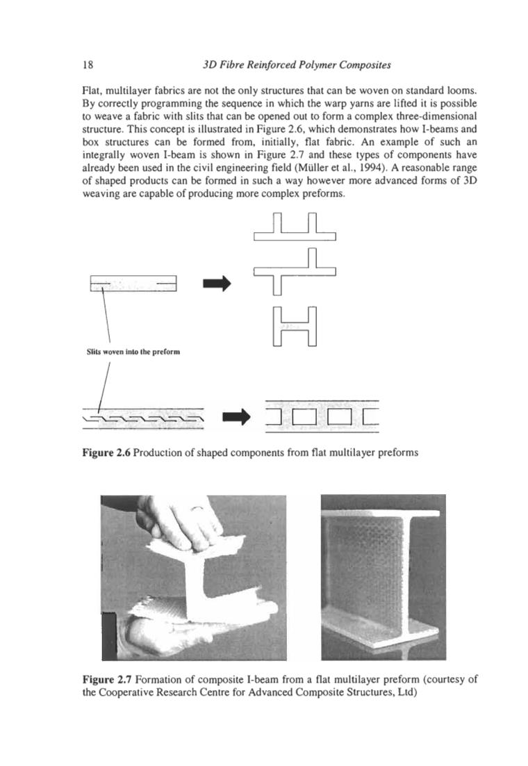
18 3D Fibre Reinforced Polymer Composites Flat,multilayer fabrics are not the only structures that can be woven on standard looms. By correctly programming the sequence in which the warp yarns are lifted it is possible to weave a fabric with slits that can be opened out to form a complex three-dimensional structure.This concept is illustrated in Figure 2.6,which demonstrates how I-beams and box structures can be formed from,initially,flat fabric.An example of such an integrally woven I-beam is shown in Figure 2.7 and these types of components have already been used in the civil engineering field (Muller et al.,1994).A reasonable range of shaped products can be formed in such a way however more advanced forms of 3D weaving are capable of producing more complex preforms. Slits woven into the preform Figure 2.6 Production of shaped components from flat multilayer preforms Figure 2.7 Formation of composite I-beam from a flat multilayer preform (courtesy of the Cooperative Research Centre for Advanced Composite Structures,Ltd)
18 30 Fibre Reinforced Polymer Composites Flat, multilayer fabrics are not the only structures that can be woven on standard looms. By correctly programming the sequence in which the warp yarns are lifted it is possible to weave a fabric with slits that can be opened out to form a complex three-dimensional structure. This concept is illustrated in Figure 2.6, which demonstrates how I-beams and box structures can be formed from, initially, flat fabric. An example of such an integrally woven I-beam is shown in Figure 2.7 and these types of components have already been used in the civil engineering field (Muller et al., 1994). A reasonable range of shaped products can be formed in such a way however more advanced forms of 3D weaving are capable of producing more complex preforms. Slits woven into the preform H Figure 2.6 Production of shaped components from flat multilayer preforms Figure 2.7 Formation of composite I-beam from a flat multilayer preform (courtesy of the Cooperative Research Centre for Advanced Composite Structures, Ltd)
Manufacture of 3D Fibre Preforms 19 In spite of some limitations in preform design with the multilayer weaving process,its greatest advantage is that it can be performed upon conventional weaving looms and does not require significant costs to develop specialised machinery.It appears suited primarily to the manufacture of large volumes of flat or simply shaped preforms with a basic0°and 90°yarn architecture. 2.2.3 3D Orthogonal Non-Wovens There is still some argument as to what constitutes the distinction between multilayer (or 3D weaving)and 3D orthogonal non-wovens.The traditional definition of weaving requires the yarns to be interlaced with each other,thus processes that produce preforms with the yarns in orthogonal,non-interlaced architectures are generally referred to as 3D orthogonal non-wovens (Khokar,1996).These processes generally differ from multilayer weaving in that multiple yarns that are separate from the warp yarns(X direction)are inserted in the Y and Z directions in a highly controlled manner.The production of a 3D fibre architecture using a 3D non-woven process therefore does not solely rely upon the warp yarn lifting sequence.Confusion can sometimes occur due to the fact that 3D weaving equipment is also capable of producing orthogonal non-woven preforms through the selection of a suitable lifting sequence.It would therefore be better to define the style of preform produced rather than the equipment used in manufacture. however this is not yet the case in the majority of the literature. Since the 1970's a wide range of processes have been developed to produce 3D orthogonal preforms.These vary from techniques utilising relatively conventional weaving mechanisms but with multiple weft insertion (Mohamed et al.,1988),to processes (Mohamed et al.,1988;Ko,1989a)that have very little in common with the traditional weaving process.Some of the earliest work in 3D orthogonal nonwovens was pioneered in France by Aerospatiale and Brochier who licensed their separately developed technology in the USA to Hercules(Btuno et al.,1986)and Avco Speciality Materials (Rolincik,1987;Mullen and Roy,1972;McAllister,and Taverna,1975) respectively.Both processes are similar in that they use an initial framework around which radial and circumferential yarns(for cylindrical preforms)or Y and Z yarns (for rectangular billets)are placed.For the Brochier process(AutoweaveTM)this framework consists of pre-cured reinforcements inserted into a phenolic foam mandrel whilst the Aerospatiale process uses a network of metallic rods and plates that are removed during the placement of the axial yarns (see Figure 2.8).Both processes are capable of producing shaped preforms by suitable shaping of the initial framework and can be used to construct 4D and 5D preforms,that is with architectures containing fibres laid in directions other than X,Y or Z.These two processes have been mostly used for the production of carbon/carbon composites for use as components in rocket motors and exit cones. Significant development of machinery to manufacture 3D non-woven preforms has also been undertaken within Japan since the 1970's,particularly at the Three-D Composites Research Corporation (a subsidiary of the Mitsubishi Electric Corporation). Methods for the production of non-woven preforms have been developed by Fukuta et al.(1974)and Kimbara et al (1991),an example of which is shown in Figure 2.9.Again these processes rely upon the insertion of yarn or cured composite rods along pre-set directions,the main difference between these methods and others being the mechanisms to control that insertion
Manufacture of 30 Fibre Preforms 19 In spite of some limitations in preform design with the multilayer weaving process, its greatest advantage is that it can be performed upon conventional weaving looms and does not require significant costs to develop specialised machinery. It appears suited primarily to the manufacture of large volumes of flat or simply shaped preforms with a basic 0" and 90" yarn architecture. 2.2.3 3D Orthogonal Non-Wovens There is still some argument as to what constitutes the distinction between multilayer (or 3D weaving) and 3D orthogonal non-wovens. The traditional definition of weaving requires the yams to be interlaced with each other, thus processes that produce preforms with the yams in orthogonal, non-interlaced architectures are generally referred to as 3D orthogonal non-wovens (Khokar, 1996). These processes generally differ from multilayer weaving in that multiple yarns that are separate from the warp yarns (X direction) are inserted in the Y and Z directions in a highly controlled manner. The production of a 3D fibre architecture using a 3D non-woven process therefore does not solely rely upon the warp yam lifting sequence. Confusion can sometimes occur due to the fact that 3D weaving equipment is also capable of producing orthogonal non-woven preforms through the selection of a suitable lifting sequence. It would therefore be better to define the style of preform produced rather than the equipment used in manufacture, however this is not yet the case in the majority of the literature. Since the 1970's a wide range of processes have been developed to produce 3D orthogonal preforms. These vary from techniques utilising relatively conventional weaving mechanisms but with multiple weft insertion (Mohamed et a]., 1988), to processes (Mohamed et al., 1988; KO, 1989a) that have very little in common with the traditional weaving process. Some of the earliest work in 3D orthogonal nonwovens was pioneered in France by Aerospatiale and Brochier who licensed their separately developed technology in the USA to Hercules (Btuno et al., 1986) and Avco Speciality Materials (Rolincik, 1987; Mullen and Roy, 1972; McAllister, and Taverna, 1975) respectively. Both processes are similar in that they use an initial framework around which radial and circumferential yarns (for cylindrical preforms) or Y and Z yarns (for rectangular billets) are placed. For the Brochier process (AutoweaveTM) this framework consists of pre-cured reinforcements inserted into a phenolic foam mandrel whilst the Aerospatiale process uses a network of metallic rods and plates that are removed during the placement of the axial yarns (see Figure 2.8). Both processes are capable of producing shaped preforms by suitable shaping of the initial framework and can be used to construct 4D and 5D preforms, that is with architectures containing fibres laid in directions other than X, Y or Z. These two processes have been mostly used for the production of carbodcarbon composites for use as components in rocket motors and exit cones. Significant development of machinery to manufacture 3D non-woven preforms has also been undertaken within Japan since the 1970's, particularly at the Three-D Composites Research Corporation (a subsidiary of the Mitsubishi Electric Corporation). Methods for the production of non-woven preforms have been developed by Fukuta et al. (1974) and Kimbara et a1 (1991), an example of which is shown in Figure 2.9. Again these processes rely upon the insertion of yam or cured composite rods along pre-set directions, the main difference between these methods and others being the mechanisms to control that insertion