15 4 SITE INFASTRUCTURE FIGURE 4.3:WHEELCLEANING ARRANGEMENTS Wheel Spinning Cleaning Unit 1NNX Collection chamber -Drain to appropriate treatment system 次77入 Shaker Bar Wheel Cleaner Shaker Bars Drain to appropriate Collection Chamber treatment system YYYYYYWYYYY Wheelwash Cleaner Water Metal Bars MY 苏> 0000000000 Drain to appropriate Concrete Base treatment system
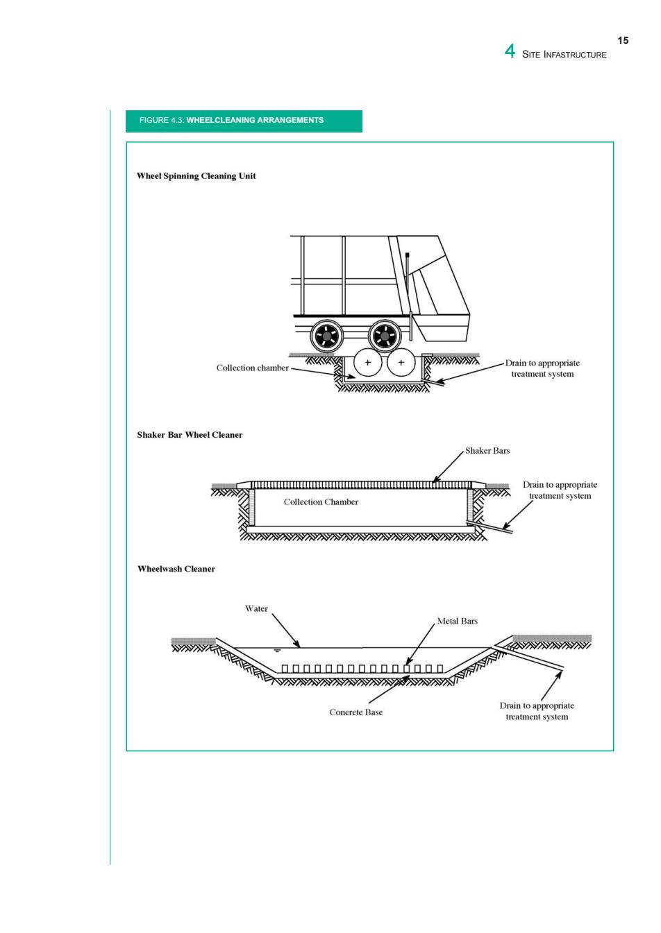
FIGURE 4.3: WHEELCLEANING ARRANGEMENTS 15 4 SITE INFASTRUCTURE
16 LANDFILL MANUALS waste oils and similar materials the need for bunding should be considered. Areas designated for storage,handling or treatment of green wastes or construction/demolition wastes should comprise of a hardstanding surface with an impervious base,peripheral bunding and access ramp.A sealed drainage system should be used to collect liquids emanating from these areas. Collected liquid should be diverted to leachate storage or treatment facilities. Civic waste facilities may also be used as bring centres for household hazardous waste (HHW)and containers for their secure deposit should be provided.Examples of HHW are:used or out of date medicines and veterinary products;household detergents;paints and solvents;primary batteries; pesticides;and herbicides.Close supervision of HHW collection is required.Civic waste facilities should be manned at all times that they are open to the public. Civic waste facilities should be landscaped so that they are aesthetically pleasing.A typical civic waste facility layout is presented in Figure 4.4. 4.8 SECURITY The landfill design should incorporate security provisions which may include the following: Fencing:Perimeter fencing should be provided at all sites.The fencing should be to an adequate standard (chainlink,palisade)and sufficient height (approximately 2.3m)to prevent unauthorised access. Gates:Access gates should be provided at the reception area.It may be necessary to provide a number of gates at points around the site for access. All gates should be to a standard similar to that of the specification for the security fencing.The gates must be secured with suitable locks. Security cameras/alarms:Security cameras may be used at the access point/reception area and at other strategic locations around the site e.g.civic waste area.Intruder alarms may be fitted to the reception facilities/compound stores and linked to a call out system
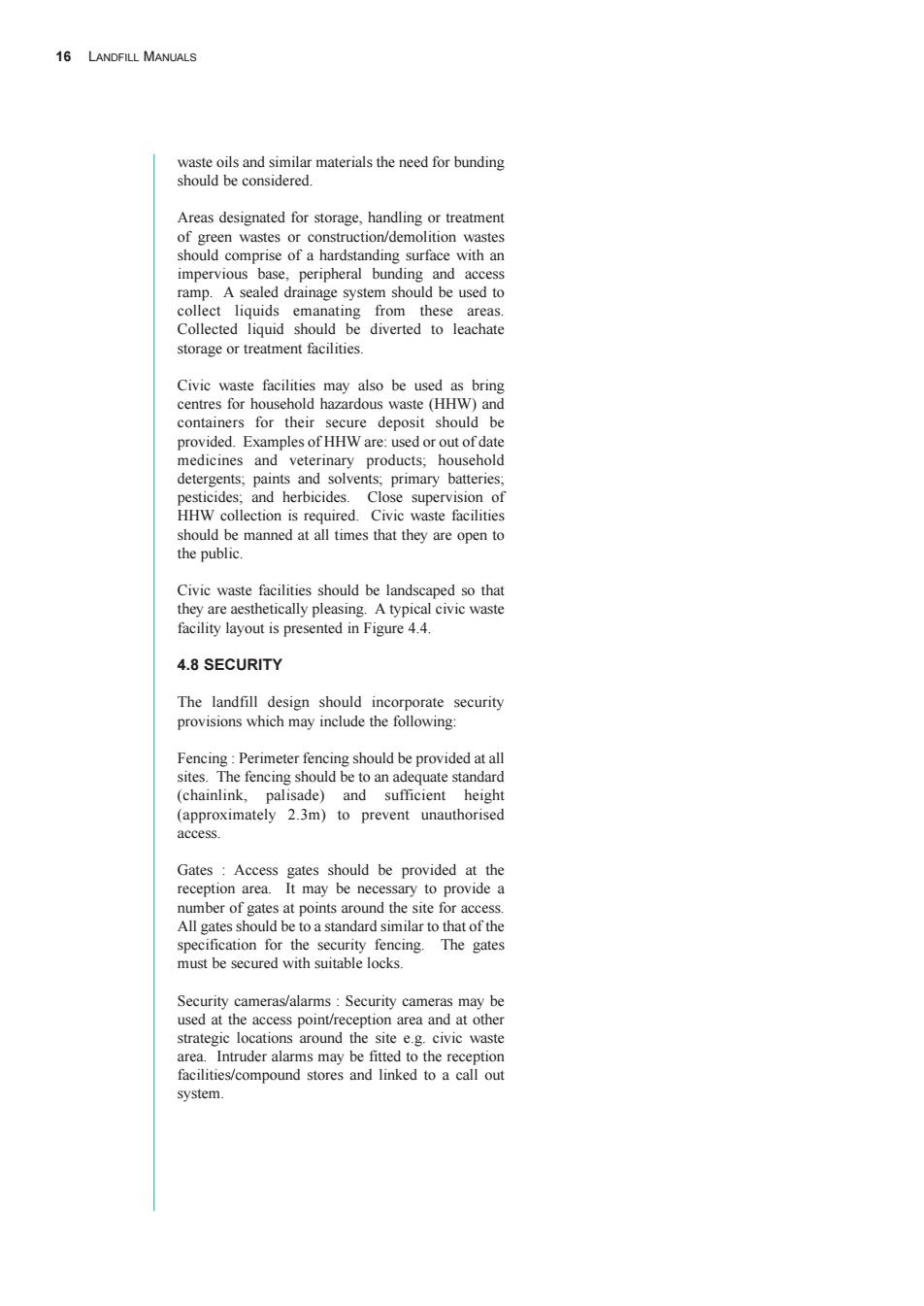
waste oils and similar materials the need for bunding should be considered. Areas designated for storage, handling or treatment of green wastes or construction/demolition wastes should comprise of a hardstanding surface with an impervious base, peripheral bunding and access ramp. A sealed drainage system should be used to collect liquids emanating from these areas. Collected liquid should be diverted to leachate storage or treatment facilities. Civic waste facilities may also be used as bring centres for household hazardous waste (HHW) and containers for their secure deposit should be provided. Examples of HHW are: used or out of date medicines and veterinary products; household detergents; paints and solvents; primary batteries; pesticides; and herbicides. Close supervision of HHW collection is required. Civic waste facilities should be manned at all times that they are open to the public. Civic waste facilities should be landscaped so that they are aesthetically pleasing. A typical civic waste facility layout is presented in Figure 4.4. 4.8 SECURITY The landfill design should incorporate security provisions which may include the following: Fencing : Perimeter fencing should be provided at all sites. The fencing should be to an adequate standard (chainlink, palisade) and sufficient height (approximately 2.3m) to prevent unauthorised access. Gates : Access gates should be provided at the reception area. It may be necessary to provide a number of gates at points around the site for access. All gates should be to a standard similar to that of the specification for the security fencing. The gates must be secured with suitable locks. Security cameras/alarms : Security cameras may be used at the access point/reception area and at other strategic locations around the site e.g. civic waste area. Intruder alarms may be fitted to the reception facilities/compound stores and linked to a call out system. 16 LANDFILL MANUALS
17 4 SITE INFASTRUCTURE FIGURE 4.4:TYPICAL CIVIC WASTE FACILITY LAYOUT 阿 Mixed Plastics P P Constructio Aluminium Cans P Waste Clear Bottles P P Green Waste Service Road Green Bottles' Brown Bottles- P White Goods CFC Recovery Paper Packaging 阿P Newsprint P Used Clothes Security Fencing 回 Waste Oils P Waste Paints- P Used Batteries tV Reception 00 Public Entrance Exit Service Entrance/Exit P=Parking Space
FIGURE 4.4: TYPICAL CIVIC WASTE FACILITY LAYOUT 17 4 SITE INFASTRUCTURE

18 LANDFILL MANUALS 5.GROUNDWATER AND SURFACE WATER MANAGEMENT 5.1 INTRODUCTION acceptability,measures to be used to minimise the pollution potential and investigation requirements,as Groundwater and surface water are major natural appropriate. resources of both ecological and economic value and their protection is of prime importance.It is 5.2.2 GROUNDWATER DIRECTIVE therefore essential that a landfill design includes provisions for the management and protection of The Waste Management Act of 1996,through the both these entities. Waste Management (Licensing)Regulations,1997 (SI No.133 of 1997),and the Local Government Information arising from the investigations will (Water Pollution)Act,1977 and subsequent assist in detailing the level of groundwater/surface amendments gives effect to 'Council Directive water management required.The sequence and 80/68/EEC on the protection of groundwater against extent of the investigation necessary is outlined in pollution caused by certain dangerous substances' the Agency's Manual 'Imvestigations for Landfills'. The purpose of this Directive is to prevent the pollution of groundwater by substances belonging to 5.2 GROUNDWATER MANAGEMENT the families and groups of substances in Lists I or II, and as far as possible to check or eliminate the Groundwater management may be required to consequence of pollution which has already minimise/prevent: occurred. interference with the groundwater regime during The Directive distinguishes between direct and the construction period; indirect discharges into groundwater.A direct discharge of substances in the lists means an damage to the liner(by uplift); introduction of the substance to groundwater without percolation through the ground or subsoil.An transport of contaminants from the landfill;and indirect discharge means the introduction of the substances on the list to groundwater after leachate generation by preventing groundwater percolation through the ground or subsoil. infiltration. It is important to note that this Directive prohibits 5.2.1 A STRATEGY FOR THE PROTECTION OF direct discharge into groundwater of List I GROUNDWATER substances(exceptions are where a survey shows the groundwater is permanently unsuitable for any other a document outlining the national strategy for use).Steps must be taken to prevent substances in Groundwater Protection was published in 1999 List I and limit substances in List II from entering entitled 'Groundwater Protection Schemes'.One of into the groundwater. the objectives of this document is to provide geological and hydrogeological information so that 5.2.3 GROUNDWATER CONTROL MEASURES potentially polluting developments can be located in less vulnerable areas and identify appropriate Information from the investigations should be used measures to minimise the potential for pollution to assess whether groundwater control is required from these activities.The strategy works through the and if so what are the effects a control system will integration of two main components,land surface have on the groundwater.Information extracted zoning and response matrices for potentially from the investigations should include: polluting activities.The land surface zoning takes account of groundwater sources,groundwater ·groundwater regime; resources (aquifers)and vulnerability to contamination.When combined the outcome is a permeability and transmissivity of all strata; groundwater protection zone.The response matrices provide recommended responses to the location of distribution,thickness and depth of subsoils and the potentially polluting activities.These responses bedrock: depend on the relative risk and describe the degree of
5.1 INTRODUCTION Groundwater and surface water are major natural resources of both ecological and economic value and their protection is of prime importance. It is therefore essential that a landfill design includes provisions for the management and protection of both these entities. Information arising from the investigations will assist in detailing the level of groundwater/surface water management required. The sequence and extent of the investigation necessary is outlined in the Agency’s Manual ‘Investigations for Landfills’. 5.2 GROUNDWATER MANAGEMENT Groundwater management may be required to minimise/prevent: • interference with the groundwater regime during the construction period; • damage to the liner (by uplift); • transport of contaminants from the landfill; and • leachate generation by preventing groundwater infiltration. 5.2.1 A STRATEGY FOR THE PROTECTION OF GROUNDWATER A document outlining the national strategy for Groundwater Protection was published in 1999 entitled ‘Groundwater Protection Schemes’. One of the objectives of this document is to provide geological and hydrogeological information so that potentially polluting developments can be located in less vulnerable areas and identify appropriate measures to minimise the potential for pollution from these activities. The strategy works through the integration of two main components, land surface zoning and response matrices for potentially polluting activities. The land surface zoning takes account of groundwater sources, groundwater resources (aquifers) and vulnerability to contamination. When combined the outcome is a groundwater protection zone. The response matrices provide recommended responses to the location of the potentially polluting activities. These responses depend on the relative risk and describe the degree of acceptability, measures to be used to minimise the pollution potential and investigation requirements, as appropriate. 5.2.2 GROUNDWATER DIRECTIVE The Waste Management Act of 1996, through the Waste Management (Licensing) Regulations, 1997 (SI No. 133 of 1997), and the Local Government (Water Pollution) Act, 1977 and subsequent amendments gives effect to ‘Council Directive 80/68/EEC on the protection of groundwater against pollution caused by certain dangerous substances’. The purpose of this Directive is to prevent the pollution of groundwater by substances belonging to the families and groups of substances in Lists I or II, and as far as possible to check or eliminate the consequence of pollution which has already occurred. The Directive distinguishes between direct and indirect discharges into groundwater. A direct discharge of substances in the lists means an introduction of the substance to groundwater without percolation through the ground or subsoil. An indirect discharge means the introduction of the substances on the list to groundwater after percolation through the ground or subsoil. It is important to note that this Directive prohibits direct discharge into groundwater of List I substances (exceptions are where a survey shows the groundwater is permanently unsuitable for any other use). Steps must be taken to prevent substances in List I and limit substances in List II from entering into the groundwater. 5.2.3 GROUNDWATER CONTROL MEASURES Information from the investigations should be used to assess whether groundwater control is required and if so what are the effects a control system will have on the groundwater. Information extracted from the investigations should include: • groundwater regime; • permeability and transmissivity of all strata; • distribution, thickness and depth of subsoils and bedrock; 5. GROUNDWATER AND SURFACE WATER MANAGEMENT 18 LANDFILL MANUALS
5 6 GROUNDWATER AND SURFACE WATER MANAGEMENT attenuation properties of the subsoil: Groundwater control can be achieved by physical exclusion or by pumping from sumps and wells. location of wells,springs,sink and swallow holes Physical exclusion control methods may include or other groundwater features; provision for an under drainage system,peripheral drains or cut-off walls.Pumping should only be groundwater contours,gradients,rates of flow. undertaken if short term control is required.An and direction of flow; example of a typical cut off drain is given in Figure 5.2 Approximate ranges of application of groundwater quality,(chemistry,and natural groundwater control techniques in soils are given in problems); Appendix B,Figure B.1.Appendix B.1 provides a list of methods for groundwater control.Further groundwater protection zones; information on groundwater control may be obtained from CIRIA Report No.113 (CIRIA,1988).This groundwater abstractions rates; report will shortly be superseded by CIRIA Report titled 'Groundwater Control:design and practice. predicted influence of short/long term dewatering, Where groundwater control measures are required, the subsequent outlet for the groundwater should be relationship with surface waters: established.This may be directly to a water body or to a retention pond if the groundwater does not meet catchment boundaries: the water quality standards of the receiving waters. groundwater vulnerability:and ·aquifer category. Maps should be provided to display the foregoing information.The identification of potentially water bearing or low permeability strata and location of the water table or piezometric level in relation to the proposed excavation is the starting point for any assessment of groundwater control needs.This will generally involve the study of borehole and trial pit logs and groundwater level records from boreholes and piezometers. The location of the landfill liner system in relation to the water table will dictate the control measures required.If the liner system is located above the water table so there is an unsaturated zone immediately below the waste the likelihood is that no groundwater control measures will be required.On the other hand if there is a relatively high water table and the liner system is located below this level groundwater control measures may be required. Examples of groundwater conditions that may occur are presented in Figure 5.1.Illustrated are the cases of: ·Outward gradient: ·Inward gradient; Perched groundwater:and Confined aquifer
• attenuation properties of the subsoil; • location of wells, springs, sink and swallow holes or other groundwater features; • groundwater contours, gradients, rates of flow, and direction of flow; • groundwater quality, (chemistry, and natural problems); • groundwater protection zones; • groundwater abstractions rates; • predicted influence of short/long term dewatering; • relationship with surface waters; • catchment boundaries; • groundwater vulnerability; and • aquifer category. Maps should be provided to display the foregoing information. The identification of potentially water bearing or low permeability strata and location of the water table or piezometric level in relation to the proposed excavation is the starting point for any assessment of groundwater control needs. This will generally involve the study of borehole and trial pit logs and groundwater level records from boreholes and piezometers. The location of the landfill liner system in relation to the water table will dictate the control measures required. If the liner system is located above the water table so there is an unsaturated zone immediately below the waste the likelihood is that no groundwater control measures will be required. On the other hand if there is a relatively high water table and the liner system is located below this level groundwater control measures may be required. Examples of groundwater conditions that may occur are presented in Figure 5.1. Illustrated are the cases of: • Outward gradient; • Inward gradient; • Perched groundwater; and • Confined aquifer. Groundwater control can be achieved by physical exclusion or by pumping from sumps and wells. Physical exclusion control methods may include provision for an under drainage system, peripheral drains or cut-off walls. Pumping should only be undertaken if short term control is required. An example of a typical cut off drain is given in Figure 5.2. Approximate ranges of application of groundwater control techniques in soils are given in Appendix B, Figure B.1. Appendix B.1 provides a list of methods for groundwater control. Further information on groundwater control may be obtained from CIRIA Report No.113 (CIRIA, 1988). This report will shortly be superseded by CIRIA Report titled ‘Groundwater Control: design and practice’. Where groundwater control measures are required, the subsequent outlet for the groundwater should be established. This may be directly to a water body or to a retention pond if the groundwater does not meet the water quality standards of the receiving waters. 19 5 GROUNDWATER AND SURFACE WATER MANAGEMENT