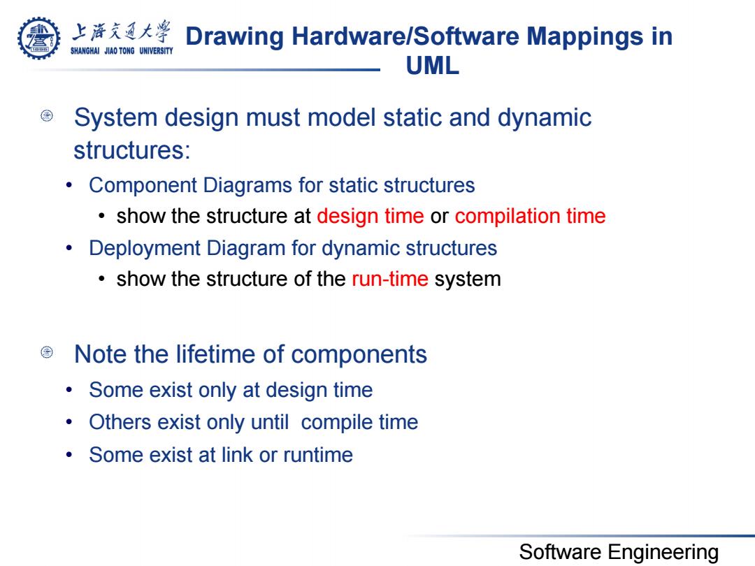
上溶充通大粤 Drawing Hardware/Software Mappings in SHANGHAI JIAO TONG UNIVERSITY UML System design must model static and dynamic structures: Component Diagrams for static structures show the structure at design time or compilation time Deployment Diagram for dynamic structures show the structure of the run-time system Note the lifetime of components Some exist only at design time Others exist only until compile time Some exist at link or runtime Software Engineering
Software Engineering Drawing Hardware/Software Mappings in UML System design must model static and dynamic structures: • Component Diagrams for static structures • show the structure at design time or compilation time • Deployment Diagram for dynamic structures • show the structure of the run-time system Note the lifetime of components • Some exist only at design time • Others exist only until compile time • Some exist at link or runtime
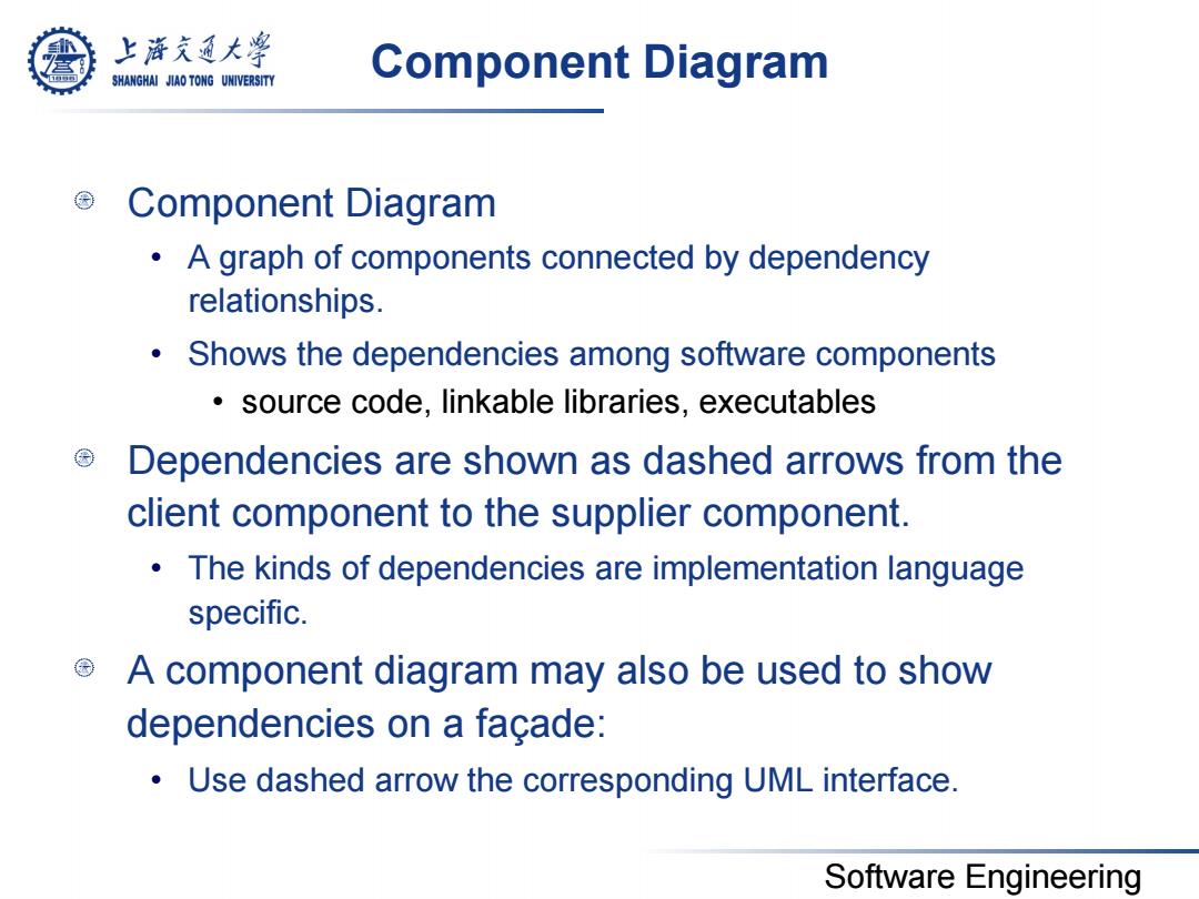
上游充通大¥ SHANGHAI JIAO TONG UNIVERSITY Component Diagram Component Diagram A graph of components connected by dependency relationships. Shows the dependencies among software components source code,linkable libraries,executables Dependencies are shown as dashed arrows from the client component to the supplier component. The kinds of dependencies are implementation language specific. A component diagram may also be used to show dependencies on a facade: Use dashed arrow the corresponding UML interface. Software Engineering
Software Engineering Component Diagram Component Diagram • A graph of components connected by dependency relationships. • Shows the dependencies among software components • source code, linkable libraries, executables Dependencies are shown as dashed arrows from the client component to the supplier component. • The kinds of dependencies are implementation language specific. A component diagram may also be used to show dependencies on a façade: • Use dashed arrow the corresponding UML interface
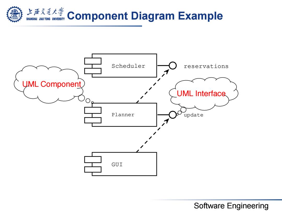
上游充通大警 SHANGHAI JIAO TONG UNIVERSITY Component Diagram Example Scheduler reservations UML Component UML Interface Planner update 名 GUI Software Engineering
Software Engineering Component Diagram Example UML Interface UML Component Scheduler Planner GUI reservations update

上游充通大学 SHANGHAI JIAO TONG UNIVERSITY Deployment Diagram Deployment diagrams are useful for showing a system design after the following decisions are made Subsystem decomposition ·Concurrency Hardware/Software Mapping A deployment diagram is a graph of nodes connected by communication associations. Nodes are shown as 3-D boxes. Nodes may contain component instances. . Components may contain objects(indicating that the object is part of the component) Software Engineering
Software Engineering Deployment Diagram Deployment diagrams are useful for showing a system design after the following decisions are made • Subsystem decomposition • Concurrency • Hardware/Software Mapping A deployment diagram is a graph of nodes connected by communication associations. • Nodes are shown as 3-D boxes. • Nodes may contain component instances. • Components may contain objects (indicating that the object is part of the component)
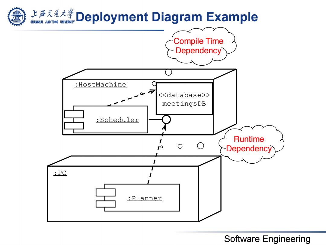
上浒充通大 SHANGHAI JIAO TONG UNIVERSITY Deployment Diagram Example Compile Time Dependency HostMachine <<database>> meetingsDB Scheduler Runtime Dependency :PC 三 :Planner Software Engineering
Software Engineering Deployment Diagram Example Runtime Dependency Compile Time Dependency :Planner :PC :Scheduler :HostMachine <<database>> meetingsDB