725 Budynas-Nisbett:Shigley's Ill.Design of Mechanical 14.Spur and Helical Gears The McGraw-Hill Mechanical Engineering Elements Companies,2008 Design,Eighth Edition 728 Mechanical Engineering Design Figure 14-4 70 Metallurgical and quality control procedures required Allowable bending stress Grade 3-2.5%Chrome numbers for nitriding steel S,=105.2Hg+29280psi gears S.The Sl equations 分60 areS,=0.594Hg+87.76 Grade 2-2.5%Chrom MPa Nitralloy grade】 S,=105.2Hn+22280psi Grade 2-Nitralloy S=0.784Hg+114.81 S,=113.8Hg+16650psi MPa Nitralloy grade 2 50 S=0.7255Hg+63.89 Grade 1-2.5%Chrome MPa 2.5%chrome,grade 1 S,=105.2Hg+9280psi S=0.7255Hg+153.63 MPa 2.5%chrome,grade 2 40 S=0.7255Hg+201.91 MPa 2.5%chrome,grade 3 Grade 1-Nitralloy S,=86.2Hg+12730psi (Source:ANSI/AGMA 2001- D04,2101-D04) 3050 275 300 325 350 Core hardness.H Table 14-3 Repeatedly Applied Bending Strength S,at 107 Cycles and 0.99 Reliability for Steel Gears Source:ANSI/AGMA 2001-D04. Minimum Allowable Bending Stress Number S,,2 Material Heat Surface Psi Designation Treatment Hardness Grade 1 Grade 2 Grade 3 Steel3 Through-hardened See Fig.14-2 See Fig.14-2 See Fig.14-2 Flame4 or induction See Table 8* 45000 55000 hardened with type A pattern5 Flame4 or induction See Table 8* 22000 22000 hardened4 with type B pattern5 Carburized and See Table 9* 55000 65000o 75000 hardened 70000° Nitrided4.7 (through- 83.5HR15N See Fig.14-3 See Fig.14-3 hardened steels) Nitralloy 135M Nitrided4.7 87.5HR15N See Fig.14-4 See Fig.14-4 See Fig.14-4 Nitralloy N,and 2.5%chrome (no aluminum) Notes:See ANSI/AGMA 2001-D04 for references cited in notes 1-7. Hardness to be equivolent to that a the roo diameter in the center of the tooth space and face width. See tables7hough 10for mjr metaffortresde of steeeas. 3The steeseleted mst bematbewith the hea psend harss equired. The allowable stress numbers indicated may be used with the case depths prescribed in 16.1. SSe figure 12for ypeA type Bhardss patems. of bainite and micocks are limited to grode 3 levels,70,000 psi may be used. The vodtyofdasis.Sincethe shapefheffeiveSNcrve slt,the sensitviyoshok should be imvestigated before ponih the desig.[7] Toblesd9of ANSI/AGMA 2001-4rcmprehensiveof the mjor metofrffngSSof flamehardddndidd (Table8) nd carburized and hardened (Toble 9)steel gears
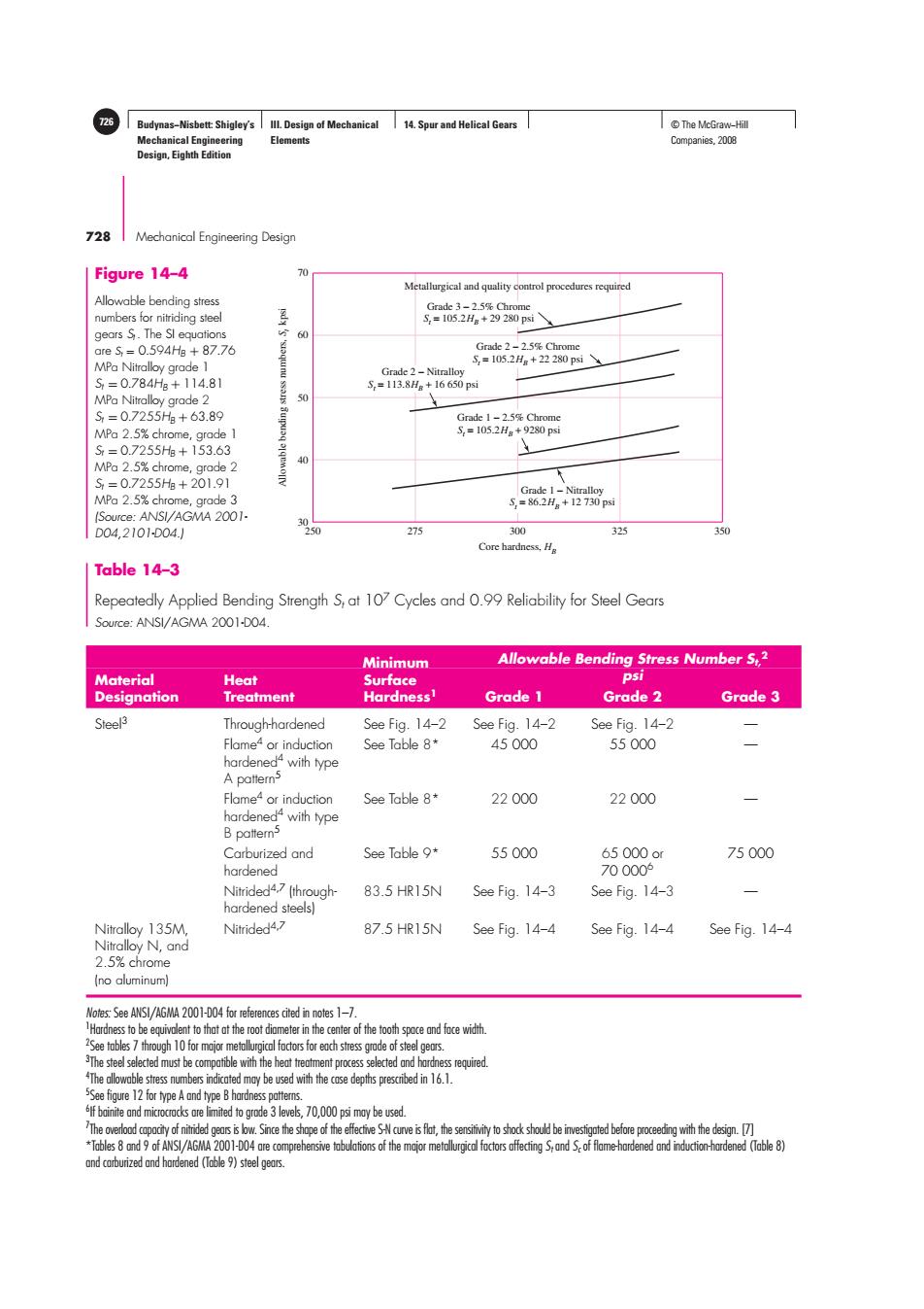
Budynas−Nisbett: Shigley’s Mechanical Engineering Design, Eighth Edition III. Design of Mechanical Elements 14. Spur and Helical Gears 726 © The McGraw−Hill Companies, 2008 728 Mechanical Engineering Design Table 14–3 Repeatedly Applied Bending Strength St at 107 Cycles and 0.99 Reliability for Steel Gears Source: ANSI/AGMA 2001-D04. Minimum Allowable Bending Stress Number St, 2 Material Heat Surface psi Designation Treatment Hardness1 Grade 1 Grade 2 Grade 3 Steel3 Through-hardened See Fig. 14–2 See Fig. 14–2 See Fig. 14–2 — Flame4 or induction See Table 8* 45 000 55 000 — hardened4 with type A pattern5 Flame4 or induction See Table 8* 22 000 22 000 — hardened4 with type B pattern5 Carburized and See Table 9* 55 000 65 000 or 75 000 hardened 70 0006 Nitrided4,7 (through- 83.5 HR15N See Fig. 14–3 See Fig. 14–3 — hardened steels) Nitralloy 135M, Nitrided4,7 87.5 HR15N See Fig. 14–4 See Fig. 14–4 See Fig. 14–4 Nitralloy N, and 2.5% chrome (no aluminum) Notes: See ANSI/AGMA 2001-D04 for references cited in notes 1–7. 1 Hardness to be equivalent to that at the root diameter in the center of the tooth space and face width. 2 See tables 7 through 10 for major metallurgical factors for each stress grade of steel gears. 3 The steel selected must be compatible with the heat treatment process selected and hardness required. 4 The allowable stress numbers indicated may be used with the case depths prescribed in 16.1. 5 See figure 12 for type A and type B hardness patterns. 6 If bainite and microcracks are limited to grade 3 levels, 70,000 psi may be used. 7 The overload capacity of nitrided gears is low. Since the shape of the effective S-N curve is flat, the sensitivity to shock should be investigated before proceeding with the design. [7] *Tables 8 and 9 of ANSI/AGMA 2001-D04 are comprehensive tabulations of the major metallurgical factors affecting St and Sc of flame-hardened and induction-hardened (Table 8) and carburized and hardened (Table 9) steel gears. Figure 14–4 Allowable bending stress numbers for nitriding steel gears St . The SI equations are St = 0.594HB + 87.76 MPa Nitralloy grade 1 St = 0.784HB + 114.81 MPa Nitralloy grade 2 St = 0.7255HB + 63.89 MPa 2.5% chrome, grade 1 St = 0.7255HB + 153.63 MPa 2.5% chrome, grade 2 St = 0.7255HB + 201.91 MPa 2.5% chrome, grade 3 (Source: ANSI/AGMA 2001- D04,2101-D04.) 250 275 300 325 350 30 40 50 60 70 Core hardness, HB Allowable bending stress numbers, St kpsi Metallurgical and quality control procedures required Grade 1 − Nitralloy St = 86.2HB + 12 730 psi Grade 1 − 2.5% Chrome St = 105.2HB + 9280 psi Grade 2 − Nitralloy St = 113.8HB + 16 650 psi Grade 2 − 2.5% Chrome St = 105.2HB + 22 280 psi Grade 3 − 2.5% Chrome St = 105.2HB + 29 280 psi
Budynas-Nisbett:Shigley's Ill.Design of Mechanical 14.Spur and Helical Gears ©The McGraw-Hil Mechanical Engineering Elements Companies,2008 Design,Eighth Edition Spur and Helical Gears 729 Table 14-4 Repeatedly Applied Bending Strength S,for Iron and Bronze Gears at 10 Cycles and 0.99 Reliability Source:ANSI/AGMA 2001-D04. Allowable Bending Material Heat Typical Minimum Stress Number,St Material Designation Treatment Surface Hardness2 psi ASTM A48 gray Class 20 As cast 5000 cast iron Class 30 As cast 174HB 8500 Class 40 As cast 201HB 13000 ASTM A536 ductile Grade60-40-18 Annealed 140HB 22000-33000 (nodular)Iron Grade80-55-06 Quenched and 179HB 22000-33000 tempered Grade100-70-03 Quenched and 229HB 27000-40000 tempered Grade120-90-02 Quenched and 269HB 31000-44000 tempered Bronze Sand cast Minimum tensile strength 5700 40000psi ASTM B-148 Heat treated Minimum tensile strength 23600 Alloy 954 90000psi Notes: See ANSI/AGMA 2004-8,Gr Mteria Heat ramnt Mnual. 2Measured hrnss to be eqiveo that which would be measureda theimeter in thectrof the oothspocenfoe width. 3The wees should be used for geeresign purpose.The upper v may be used whe High quality materia is used. Section size and design allow maximum response to heat treatment. Proper qualityc is effected by odequate inspection. Operating experience justifes their use. The equation for the allowable bending stress is YN SE KTKR (U.S.customary units) Oall= S YN (14-17刀 (SI units) SE YeYz where for U.S.customary units(SI units), S,is the allowable bending stress,Ibf/in2(N/mm2) Yy is the stress cycle factor for bending stress Kr (Ye)are the temperature factors KR (Yz)are the reliability factors Sp is the AGMA factor of safety,a stress ratio
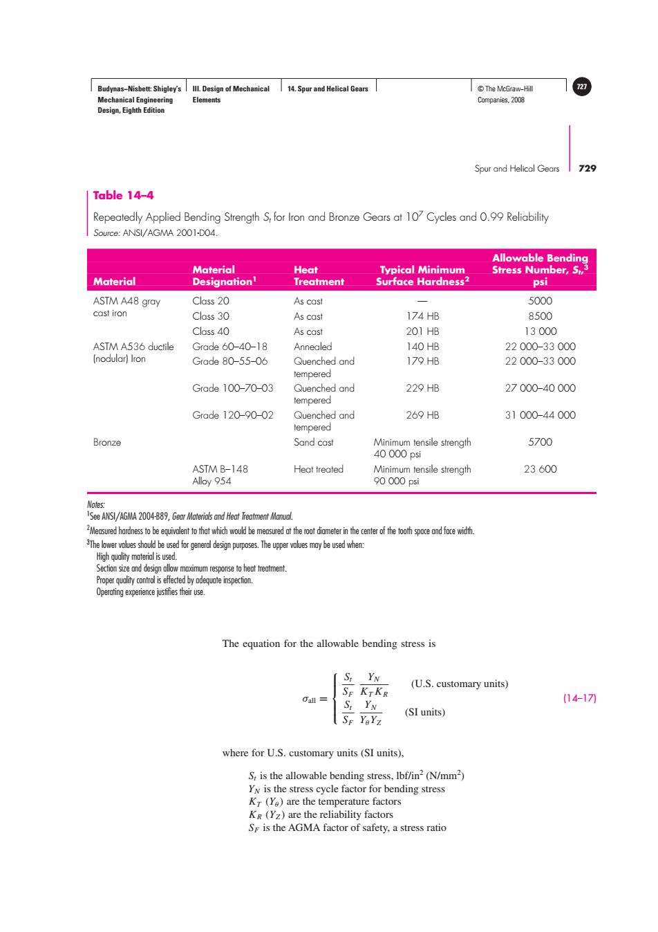
Budynas−Nisbett: Shigley’s Mechanical Engineering Design, Eighth Edition III. Design of Mechanical Elements 14. Spur and Helical Gears © The McGraw−Hill 727 Companies, 2008 Spur and Helical Gears 729 The equation for the allowable bending stress is σall = ⎧ ⎪⎪⎨ ⎪⎪⎩ St SF YN KT KR (U.S. customary units) St SF YN YθYZ (SI units) (14–17) where for U.S. customary units (SI units), St is the allowable bending stress, lbf/in2 (N/mm2 ) YN is the stress cycle factor for bending stress KT (Yθ ) are the temperature factors KR (YZ ) are the reliability factors SF is the AGMA factor of safety, a stress ratio Allowable Bending Material Heat Typical Minimum Stress Number, St, 3 Material Designation1 Treatment Surface Hardness2 psi ASTM A48 gray Class 20 As cast — 5000 cast iron Class 30 As cast 174 HB 8500 Class 40 As cast 201 HB 13 000 ASTM A536 ductile Grade 60–40–18 Annealed 140 HB 22 000–33 000 (nodular) Iron Grade 80–55–06 Quenched and 179 HB 22 000–33 000 tempered Grade 100–70–03 Quenched and 229 HB 27 000–40 000 tempered Grade 120–90–02 Quenched and 269 HB 31 000–44 000 tempered Bronze Sand cast Minimum tensile strength 5700 40 000 psi ASTM B–148 Heat treated Minimum tensile strength 23 600 Alloy 954 90 000 psi Notes: 1 See ANSI/AGMA 2004-B89, Gear Materials and Heat Treatment Manual. 2 Measured hardness to be equivalent to that which would be measured at the root diameter in the center of the tooth space and face width. 3 The lower values should be used for general design purposes. The upper values may be used when: High quality material is used. Section size and design allow maximum response to heat treatment. Proper quality control is effected by adequate inspection. Operating experience justifies their use. Table 14–4 Repeatedly Applied Bending Strength St for Iron and Bronze Gears at 107 Cycles and 0.99 Reliability Source: ANSI/AGMA 2001-D04