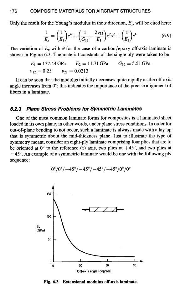
176 COMPOSITE MATERIALS FOR AIRCRAFT STRUCTURES Only the result for the Young's modulus in the x direction,E will be cited here: =()+(+() (6.9) The variation of Ex with for the case of a carbon/epoxy off-axis laminate is shown in Figure 6.3.The material constants of the single ply were taken to be E1=137.44GPa E2=11.71GPa G12=5.51GPa V12=0.25 21=0.0213 It can be seen that the modulus initially decreases quite rapidly as the off-axis angle increases from 0;this indicates the importance of the precise alignment of fibers in a laminate. 6.2.3 Plane Stress Problems for Symmetric Laminates One of the most common laminate forms for composites is a laminated sheet loaded in its own plane,in other words,under plane stress conditions.In order for out-of-plane bending to not occur,such a laminate is always made with a lay-up that is symmetric about the mid-thickness plane.Just to illustrate the type of symmetry meant,consider an eight-ply laminate comprising four plies that are to be oriented at 0 to the reference (x)axis,two plies at +45,and two plies at -45.An example of a symmetric laminate would be one with the following ply sequence: 0°/0°/+45°/-45°/-45°/+45°/0°/0° 150 100 50 0 0 30 60 90 Off-axis angle (degrees) Fg.6.3 Extensional modulus off-axis laminate
176 COMPOSITE MATERIALS FOR AIRCRAFT STRUCTURES Only the result for the Young's modulus in the x direction, Ex, will be cited here: 1(~_.~) (1 2vle~c2s e(l~s 4 -- = c a + + (6.9) Ex 4: el / \E2/ The variation of Ex with 0 for the case of a carbon/epoxy off-axis laminate is shown in Figure 6.3. The material constants of the single ply were taken to be E1 = 137.44GPa E2 = 11.71GPa Gl2 = 5.51GPa 1)12 : 0.25 1)21 = 0.0213 It can be seen that the modulus initially decreases quite rapidly as the off-axis angle increases from 0°; this indicates the importance of the precise alignment of fibers in a laminate. 6.2.3 Plane Stress Problems for Symmetric Laminates One of the most common laminate forms for composites is a laminated sheet loaded in its own plane, in other words, under plane stress conditions. In order for out-of-plane bending to not occur, such a laminate is always made with a lay-up that is symmetric about the mid-thickness plane. Just to illustrate the type of symmetry meant, consider an eight-ply laminate comprising four plies that are to be oriented at 0 ° to the reference (x) axis, two plies at +45 °, and two plies at - 45 °. An example of a symmetric laminate would be one with the following ply sequence: 0°/0°/+45°/-45°/-45o/+45o/00/0 ° E X (GPa) i 50 0 J 0 90 1 J ]0 6O Off~is a~J!e (.rfi~-grlze~) Fig. 6.3 Extensional modulus off-axis laminate

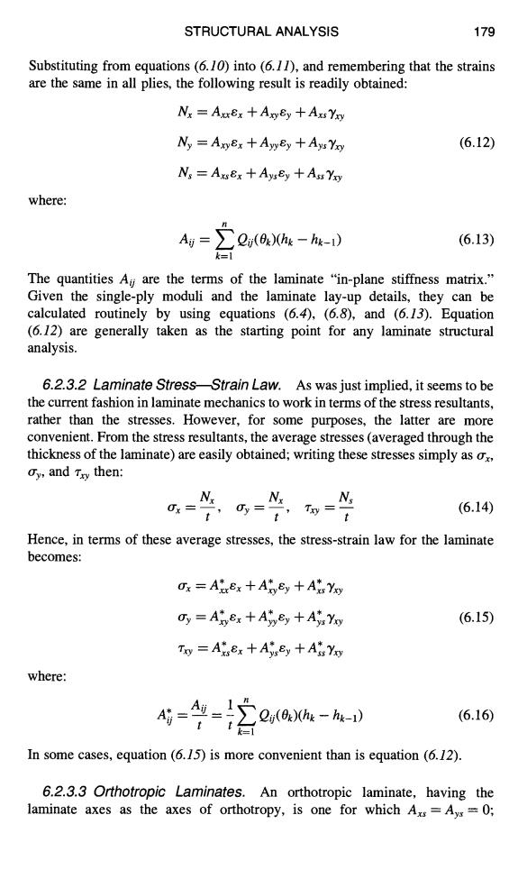
STRUCTURAL ANALYSIS 177 On the other hand,an example of an unsymmetric arrangement of the same plies would be: 0°/0°/0°/0°/+45°/-45°/+45°/-45° These two cases are shown in Figure 6.4 where z denotes the coordinate in the thickness direction. 6.2.3.1 Laminate Stiffness Matrix.Consider now a laminate comprising n plies and denote the angle between the fiber direction in the kth ply and thex laminate axis by (with the convention defined in Fig.6.2).Subject only to the symmetry requirement,the ply orientation is arbitrary.It is assumed that,when the plies are molded into the laminate,a rigid bond (of infinitesimal thickness)is formed between adjacent plies.As a consequence of this assumption,it follows that under plane stress conditions the strains are the same at all points on a line through the thickness (i.e.,they are independent of z).Denoting these strains by ex,and y,it then follows from equation(6.7)that the stresses in the kth ply will be given by: x(k)=Qx(0x)Ex+Oxy(0x)Ey +Qxs(0x)Yxy y(k)=Qxy(0x)Ex +Qy()Ey +Qys(0x)Yy (6.10) Tx(k)=Qxs(0x)Ex+ys(0x)Ey+Qxs(0x)Yxy The laminate thickness is denoted by t and the thickness of the kth ply is h-h-1 with hi defined in Figure 6.5.Assuming all plies are of the same thickness (which is the usual situation),then the thickness of an individual ply is simply t/n.Now consider an element of the laminate with sides of unit length parallel to thex-and y-axes.The forces on this element will be denoted by NN 0 -45 0 +45 +45 -45 Mid-plane -45 +45 Mid-plane -45 0 +45 0 0 0 0 0 Fig.6.4 Symmetric (left)and non-symmetric (right)eight-ply laminates
STRUCTURAL ANALYSIS 177 On the other hand, an example of an unsymmetric arrangement of the same plies would be: O°lO°lO°lO° 1+45°1-45°1+45ol-45 ° These two cases are shown in Figure 6.4 where z denotes the coordinate in the thickness direction. 6.2.3. I Laminate Stiffness Matrix. Consider now a laminate comprising n plies and denote the angle between the fiber direction in the kth ply and the x laminate axis by Ok (with the convention defined in Fig. 6.2). Subject only to the symmetry requirement, the ply orientation is arbitrary. It is assumed that, when the plies are molded into the laminate, a rigid bond (of infinitesimal thickness) is formed between adjacent plies. As a consequence of this assumption, it follows that under plane stress conditions the strains are the same at all points on a line through the thickness (i.e., they are independent of z). Denoting these strains by ex, ey, and "Yxy, it then follows from equation (6. 7) that the stresses in the kth ply will be given by: O'x(k) = Q~( Ok)ex + axy( Ok)l?,y + Qxs( Ok)3'xy ~ry(k) = Qxy( ODex + ayy( Ok)f,y + Qys( Ok)'Yxy (6.10) "rxy(k) = Qxs( Ok)ex + ays( Ok)Sy + Qss( Ok)Yxy The laminate thickness is denoted by t and the thickness of the kth ply is hk -- hk-1 with hi defined in Figure 6.5. Assuming all plies are of the same thickness (which is the usual situation), then the thickness of an individual ply is simply t/n. Now consider an element of the laminate with sides of unit length parallel to the x- and y-axes. The forces on this element will be denoted by Nx, Ny, 0 0 *,kS Mid-plane - 45 -4.5 ",~.S 0 0 ~Z mw -45 *t.5 -45 * `k5 Mid-plane Fig. 6.4 Symmetric (left) and non-symmetric (right) eight-ply laminates

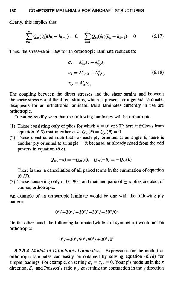
178 COMPOSITE MATERIALS FOR AIRCRAFT STRUCTURES h n=t/2 h k Ply k h k-1 midplane Ply 2 Ply 1 h o=-t/2 Fig.6.5 Ply coordinates in the thickness direction,plies numbered from the bottom surface. and N,(Figure 6.6);the N are generally termed stress resultants and have the dimension"force per unit length."Elementary equilibrium considerations give M=2a-山N=2o物-山 心=2h-) (6.11) Ny Nx Fig.6.6 Stress resultants
178 COMPOSITE MATERIALS FOR AIRCRAFT STRUCTURES h n=t/2 hk h k-I hi h 0=-if2 Ply k ,.- y midplane Ply 2 Ply 1 T t 1 Fig. 6.5 Ply coordinates in the thickness direction, plies numbered from the bottom surface. and Ns, (Figure 6.6); the N are generally termed stress resultants and have the dimension "force per unit length." Elementary equilibrium considerations give n Nx = ~ O'x(k)(hk - hk-1), k=l Ns = ~ Zxy(k)(hk - hk- 1) (6.11) k=l Ny = ~ O'y(k)(hk - hk-1), k=l 't_ X Ny l ~ Nxy -1 Fig. 6.6 Stress resultants. Nx
STRUCTURAL ANALYSIS 179 Substituting from equations(6.10)into(6.11),and remembering that the strains are the same in all plies,the following result is readily obtained: Nx AuEx +AxEy +Axs Yxy Ny =AxyEx +Ayyy +Ays Yo (6.12) N:AxsEx +Aysy +Ass Yxy where: Ag=>Qu(0x)(hk-hg-1) (6.13) k= The quantities Ay are the terms of the laminate "in-plane stiffness matrix." Given the single-ply moduli and the laminate lay-up details,they can be calculated routinely by using equations (6.4),(6.8),and (6.13).Equation (6.12)are generally taken as the starting point for any laminate structural analysis. 6.2.3.2 Laminate Stress-Strain Law.As was just implied,it seems to be the current fashion in laminate mechanics to work in terms of the stress resultants, rather than the stresses.However,for some purposes,the latter are more convenient.From the stress resultants,the average stresses(averaged through the thickness of the laminate)are easily obtained;writing these stresses simply as ox, dy,and Try then: 0x= t (6.14) Hence,in terms of these average stresses,the stress-strain law for the laminate becomes: Ox Atex Aryey Ars Yoy y=Atyex +Ayyey+Ays Yo (6.15) Tg=AtEx十A,Ey+AxY where: 2(0)hk-hk-i) (6.16) In some cases,equation (6.15)is more convenient than is equation (6.12). 6.2.3.3 Orthotropic Laminates.An orthotropic laminate,having the laminate axes as the axes of orthotropy,is one for which Axs=Ays=0;
STRUCTURAL ANALYSIS 179 Substituting from equations (6.10) into (6.11), and remembering that the strains are the same in all plies, the following result is readily obtained: Nx = Axxex + Axyey + AxsYxy Ny = Axyex + Ayyey "t- Ays Yxy (6.12) Ns = Axsex -t'-Ayse, y + Ass'Yxy where: Aij = XZ, Qij( Ok)(hk -- hk-1) (6.13) k=l The quantities A o are the terms of the laminate "in-plane stiffness matrix." Given the single-ply moduli and the laminate lay-up details, they can be calculated routinely by using equations (6.4), (6.8), and (6.13). Equation (6.12) are generally taken as the starting point for any laminate structural analysis. 6.2.3.2 Laminate Stress--Strain Law. As was just implied, it seems to be the current fashion in laminate mechanics to work in terms of the stress resultants, rather than the stresses. However, for some purposes, the latter are more convenient. From the stress resultants, the average stresses (averaged through the thickness of the laminate) are easily obtained; writing these stresses simply as o'x, try, and 7xy then: Nx Nx N, O'x=-- , O'y = --, "/'xy = -- (6.14) t t t Hence, in terms of these average stresses, the stress-strain law for the laminate becomes: O-x = Axxex + Axyey "l- Axs ]txy Or y = Axy 8 x -t- Ayy ~ y --I- Ays 'Yxy (6.15) where: "rxy = A*xsex + Aysey + Ass'Yxy AU 1 A~j =--= - ~ Qij(Ok)(hk -- hk-1) (6.16) t tk= 1 In some cases, equation (6.15) is more convenient than is equation (6.12). 6.2.3.30rthotropic Laminates. An orthotropic laminate, having the laminate axes as the axes of orthotropy, is one for which Axs = Ays = O;
180 COMPOSITE MATERIALS FOR AIRCRAFT STRUCTURES clearly,this implies that: ∑2a()hk-hk-i)=0, >Qys(0k)(hg-hg-1)=0 (6.17) k=1 Thus,the stress-strain law for an orthotropic laminate reduces to: x=At8x+A刘Ey Oy Atyex +Ayyey (6.18) Txy =Ais Yo The coupling between the direct stresses and the shear strains and between the shear stresses and the direct strains,which is present for a general laminate, disappears for an orthotropic laminate.Most laminates currently in use are orthotropic. It can be readily seen that the following laminates will be orthotropic: (1)Those consisting only of plies for which 6=0 or 90;here it follows from equation (6.8)that in either case ()=vs(6)=0. (2)Those constructed such that for each ply oriented at an angle 6,there is another ply oriented at an angle -0;because,as already noted from the odd powers in equation(6.8), 2x(-)=-Qxx(),Qyx(-)=-2s(0 There is then a cancellation of all paired terms in the summation of equation (6.17). (3)Those consisting only of 0°,9o°,and matched pairs of±0 plies are also,.of course,orthotropic. An example of an orthotropic laminate would be one with the following ply pattern: 0°/+30°/-30°/-30°/+30°/0 On the other hand,the following laminate (while still symmetric)would not be orthotropic: 0°/+30°/90°/90°/+30°/0° 6.2.3.4 Moduli of Orthotropic Laminates.Expressions for the moduli of orthotropic laminates can easily be obtained by solving equation (6.18)for simple loadings.For example,on setting oy=Txy=0,Young's modulus in the x direction,E,and Poisson's ratio vxy governing the contraction in the y direction
180 COMPOSITE MATERIALS FOR AIRCRAFT STRUCTURES clearly, this implies that: n Qxs(Ok)(hk -- hk-l) = O, k=l ~-~ Qys( Ok)(hk -- hk-1) = 0 (6.17) k=l Thus, the stress-strain law for an orthotropic laminate reduces to: O'x = Axxex + Axysy O'y = Axy ex + Ayy ~y (6.18) Txy = A,* Yxy The coupling between the direct stresses and the shear strains and between the shear stresses and the direct strains, which is present for a general laminate, disappears for an orthotropic laminate. Most laminates currently in use are orthotropic. It can be readily seen that the following laminates will be orthotropic: (1) Those consisting only of plies for which 0 = 0 ° or 90°; here it follows from equation (6.8) that in either case Qxs(O) = Qys(0) = 0. (2) Those constructed such that for each ply oriented at an angle 0, there is another ply oriented at an angle - 0; because, as already noted from the odd powers in equation (6.8), Qxs(-O)=-Qxs(O), Qys(-O)=-Qys(O) There is then a cancellation of all paired terms in the summation of equation (6.17). (3) Those consisting only of 0 °, 90 °, and matched pairs of + 0 plies are also, of course, orthotropic. An example of an orthotropic laminate would be one with the following ply pattern: 0°/+30°/-30°/-30°/+30°/0 ° On the other hand, the following laminate (while still symmetric) would not be orthotropic: 0°1+30°190°190°1+30°/0° 6.2.3.4 Modufi of Orthotropic Laminates. Expressions for the moduli of orthotropic laminates can easily be obtained by solving equation (6.18) for simple loadings. For example, on setting try = "rxy = 0, Young's modulus in the x direction, Ex, and Poisson's ratio Vxy governing the contraction in the y direction