304 COMPOSITE MATERIALS FOR AIRCRAFT STRUCTURES capacity (see Fig.9.4),which is: Y=Ye+Yp (9.9) As shown in Figure 9.7,a plastic zone length d develops in addition to the elastic zone length 3/B. Thus,the maximum load transfer capacity is: (9.10) The length of the plastic zone at failure of the adhesive is given by: -0+2(》-] (9.11) Using these equations,it can be shown3 that the maximum load that can be applied to adherend 2 without failing the adhesive is given by: Pm=2(+器](告+r] (9.12a) and,for thermal mismatch, Pmax=Pmax +E2t2(a1-@2)AT (9.12b) The area under the shear stress-strain curve for the adhesive appears explicitly within the second square bracket in equation(9.12a).This suggests that the load transfer capability should not change significantly with temperature because experimental studies on stress/strain behavior (for ductile structural film adhesives)show that this area does not vary greatly with temperature.The area under the shear stress-strain curve multiplied by the adhesive thickness ta is a measure of the maximum fracture energy per unit area of crack growth,as discussed in more detail later. The length required to transfer the load,Tmax,is now given by: 3 Lmin =dma (9.13) The minimum transfer length Lmin required to transfer T under arbitrary external load P is [based on equation(9.10)]obtained as follows: nds-nd+ also: T°=P/1+E22/E1t1)
304 COMPOSITE MATERIALS FOR AIRCRAFT STRUCTURES capacity (see Fig. 9.4), which is: 3' = 3'e + 3'~ (9.9) As shown in Figure 9.7, a plastic zone length d develops in addition to the elastic zone length 3/fl. Thus, the maximum load transfer capacity is: Tl~max = "re dac e + 'rp e-13Xedxe = "rpdmax + 're (9.10) The length of the plastic zone at failure of the adhesive 11 is given by: 1[( 2(3"e~ \-~-e / / 1/2 1] ] dmax = ~ 1+ - (9.11) Using these equations, it can be shown 3 that the maximum load that can be applied to adherend 2 without failing the adhesive is given by: ~]11/2 Pmax={[2tAE2t2(l+E2t2"]]['rP(~ +/~ltlf] 3'p)] / (9.12a) and, for thermal mismatch, r Pmax = Pmax + Eztz(al - az)AT (9.12b) The area under the shear stress-strain curve for the adhesive appears explicitly within the second square bracket in equation (9.12a). This suggests that the load transfer capability should not change significantly with temperature because experimental studies on stress/strain behavior (for ductile structural film adhesives) show that this area does not vary greatly with temperature. The area under the shear stress-strain curve multiplied by the adhesive thickness tA is a measure of the maximum fracture energy per unit area of crack growth, as discussed in more detail later. The length required to transfer the load, T~tmax, is now given by: 3 Lmin = dmax + ~ (9.13) The minimum transfer length Lmi n required to transfer T~I under arbitrary external load P is [based on equation (9.10)] obtained as follows: T~ = rdx = "rpd + R also: T~ = P/(1 + E2t2/Eltl)
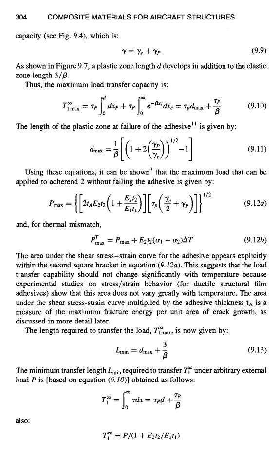
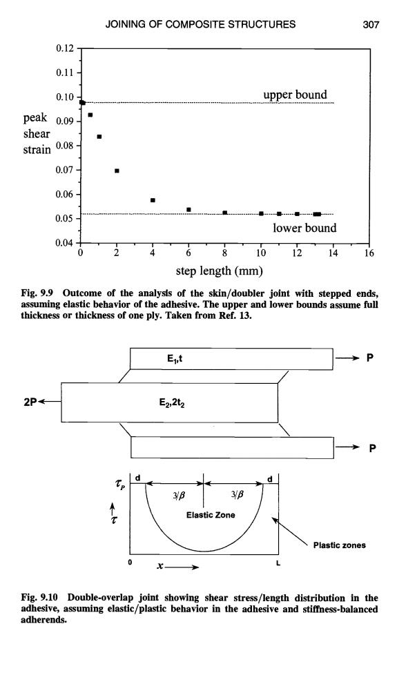
JOINING OF COMPOSITE STRUCTURES 305 and since: Lmin =d+ 3 B then: Lmin=P/rp(1+E22/E1'1】+2/β (9.14) 9.3.4.3 End-Termination Shape.The above models have assumed that the doubler(adherend 1)is of constant thickness.However,if its ends are tapered, the peak shear(and peel)stresses can be greatly reduced.This can be achieved by forming an end taper (or scarf)or,as illustrated in Figure 9.8,by stepping. Stepping is the usual configuration for composite joints since it arises naturally when laminating. An analysis for the stress distribution in doublers with scarfed stepped skin ends is described by Chalkly13.Figure 9.8 illustrates part of the model used,and Figure 9.9 is a plot,for the elastic case,of step thickness versus peak shear strain in the adhesive,assuming a step thickness of 0.13 mm and material properties for the composite boron/epoxy;the maximum thickness is 0.65 mm.The peak shear strain asymptotes to a lower bound of about half the peak level after a step length of about 5 mm.Actually,in most practical doubler applications,a step length of approximately 3 mm is used.The peel stress in the adhesive will also be markedly reduced by stepping.Stepping (or scarfing)the ends of the doubler is required in most practical applications,unless the doubler is less than a few plies thick. A useful estimate of the influence of stepping the ends of the doubler can be obtained using the simple analysis for a constant-thickness doubler,outlined in Figure 9.5.The results are shown as the bounds in Figure 9.9,taking the minimum thickness to be one ply and the maximum thickness that of the full five plies.The step length required to achieve the lower bound is of the order of 4 mm, which is about the minimum length required for full load transfer(3/B). It is of note that,for a similar thickness doubler and tapering distance,the analysis shows that the step configuration develops a lower peak shear strain than the scarfed configuration. 9.3.5 Double-Overlap Joint Figure 9.10 shows schematically one side of a simple double-overlap joint.It is assumed in this diagram that the adherends are of similar (balanced)stiffness,the product of modulus and thickness(Et).At the left end,where the outer adherend terminates,the load distribution is identical to that in the skin-doubler joint shown in Figure 9.5.At the right end,where the inner adherend terminates,the load remaining in the inner adherend is transferred to the outer adherend-this configuration is Figure 9.5,inverted
JOINING OF COMPOSITE STRUCTURES 305 and since: then: 3 Lmin = d + - /3 Lmin = P/[zp(1 + E2t2/Eltl)] + 2//3 (9.14) 9.3.4.3 End-Termination Shape. The above models have assumed that the doubler (adherend 1) is of constant thickness. However, if its ends are tapered, the peak shear (and peel) stresses can be greatly reduced. This can be achieved by forming an end taper (or scarf) or, as illustrated in Figure 9.8, by stepping. Stepping is the usual configuration for composite joints since it arises naturally when laminating. An analysis for the stress distribution in doublers with scarfed stepped ski~ ends is described by Chalkly 13. Figure 9.8 illustrates part of the model used, and Figure 9.9 is a plot, for the elastic case, of step thickness versus peak shear strain in the adhesive, assuming a step thickness of 0.13 mm and material properties for the composite boron/epoxy; the maximum thickness is 0.65 mm. The peak shear strain asymptotes to a lower bound of about half the peak level after a step length of about 5 nun. Actually, in most practical doubler applications, a step length of approximately 3 nun is used. The peel stress in the adhesive will also be markedly reduced by stepping. Stepping (or scarfing) the ends of the doubler is required in most practical applications, unless the doubler is less than a few plies thick. A useful estimate of the influence of stepping the ends of the doubler can be obtained using the simple analysis for a constant-thickness doubler, outlined in Figure 9.5. The results are shown as the bounds in Figure 9.9, taking the minimum thickness to be one ply and the maximum thickness that of the full five plies. The step length required to achieve the lower bound is of the order of 4 mm, which is about the minimum length required for full load transfer (3//3). It is of note that, for a similar thickness doubler and tapering distance, the analysis shows that the step configuration develops a lower peak shear strain than the scarfed configuration. 9.3.5 Double-Overlap Joint Figure 9.10 shows schematically one side of a simple double-overlap joint. It is assumed in this diagram that the adherends are of similar (balanced) stiffness, the product of modulus and thickness (Et). At the left end, where the outer adherend terminates, the load distribution is identical to that in the skin-doubler joint shown in Figure 9.5. At the right end, where the inner adherend terminates, the load remaining in the inner adherend is transferred td the outer adherend this configuration is Figure 9.5, inverted

器 step (n-1)uir,Tire E1,01 P E,【2Cz 1111 P u 4+(ax 41%1 >石+(ra tAX COMPOSITE MATERIALS FOR AIRCRAFT STRUCTURES u →+(rax △X △X Fig.9.8 Skin-doubler joint with stepped ends,showing part of the analytical model
306 COMPOSITE MATERIALS FOR AIRCRAFT STRUCTURES a,, I r~ J I "! ! ll.l
JOINING OF COMPOSITE STRUCTURES 307 0.12 0.11 0.10 upper bound peak 0.09 shear ◆ strain 0.08 0.07- ◆ 0.06 0.05 lower bound 0.04 0 6 10121416 step length (mm) Fig.9.9 Outcome of the analysis of the skin/doubler joint with stepped ends, assuming elastic behavior of the adhesive.The upper and lower bounds assume full thickness or thickness of one ply.Taken from Ref.13. Eut 2P E2,2 d 3B 3/B A Elastic Zone Plastic zones 0 Fig.9.10 Double-overlap joint showing shear stress/length distribution in the adhesive,assuming elastic/plastic behavior in the adhesive and stiffness-balanced adherends
JOINING OF COMPOSITE STRUCTURES 307 0.12 0.11 0.10 peak 0.09 shear strain 0.08 0.07 0.06 0.05 0.04 upper bound II" ..................................................................................................................... ................................................................... It .............. I------I------I------IlF ..... lower bound o ~ ~ ; ~ 1'o 1'2 1'4 step length (mm) 16 Fig. 9.9 Outcome of the analysis of the skin/doubler joint with stepped ends, assuming elastic behavior of the adhesive. The upper and lower bounds assume full thickness or thickness of one ply. Taken from Ref. 13. 2P< /J El't l E2,2t 2 T \ I "P 0 L X > Plastic zones Fig. 9.10 Double-overlap joint showing shear stress/length distribution in the adhesive, assuming elastic/plastic behavior in the adhesive and stiffness-balanced adherends

308 COMPOSITE MATERIALS FOR AIRCRAFT STRUCTURES 9.3.5.1 Overlap-Length,Balanced Joint.Figure 9.10 shows schematically the shear stress distribution in the adhesive in the double-overlap joint.To minimize the weight penalty in the joint,it is desirable to use the shortest possible overlap length,with some allowance for defects and damage.The minimum overlap length, Lmin,for P<Pmax,is estimated as follows. We have that: Lmin =2d+6/B minimum transfer length and: Timax =2Tpd+2Tp/B=P maximum load transferred S0: d=P/2Tp-1/B For adherend 1,failure P=P=oiut1. Thus, Lmin =utl 4 (9.15) Alternatively,for composites,it is usual to work to an ultimate design strain level eu,typically 4000 microstrain.The strain capacity to failure exceeds this value markedly,typically up to 13,000 microstrain,but this much more modest value allows for strength reduction due to damage and stress concentrations. Then(per unit width of the joint): Pu E1Eut (9.16) Here Pu is half the total load applied to the joint.Then: Lmin E1eut1/Tp +4/B (9.17) In this case,since E=E2 and the total thickness of the outer adherends equals the inner adherend =21,B is simplified in equation (9.3)to B=√2GA/tAEi. However,longer overlaps are highly desirable(if cost and weight penalties are not too great)because they provide high levels of damage tolerance to voids and other flaws.It is important that the minimum value of shear stress Tmin not exceed about Tp/10,which approximately corresponds with the elastic trough of length 3/B. As overlap lengths decrease below Lmin,the minimum shear stress in the elastic troughTmin gradually increases until it becomes uniform(can reach a maximum level of Tp when the whole adhesive layer becomes plastic).This results in 1)a loss of damage tolerance because the joint strength is sensitive to bond length,and 2)a susceptibility to creep strain accumulation
308 COMPOSITE MATERIALS FOR AIRCRAFT STRUCTURES 9.3.5.1 Overlap-Length, Balanced Joint. Figure 9.10 shows schematically the shear stress distribution in the adhesive in the double-overlap joint. To minimize the weight penalty in the joint, it is desirable to use the shortest possible overlap length, with some allowance for defects and damage. The minimum overlap length, Lmin, for P < Pmax, is estimated as follows. We have that: Lmin = 2d + 6//3 minimum transfer length and: T1 max = 2zed + 2"re~~3 = P maximum load transferred so: d = e/2.rp - 1//3 For adherend 1, failure P = Pu = ~lutl. Thus, Criutl 4 Lm~n-- ¢ (9.15) zp /3 Alternatively, for composites, it is usual to work to an ultimate design strain level eu, typically 4000 microstrain. The strain capacity to failure exceeds this value markedly, typically up to 13,000 microstrain, but this much more modest value allows for strength reduction due to damage and stress concentrations. Then (per unit width of the joint): Pu = Eleutl (9.16) Here Pu is half the total load applied to the joint. Then: Lmin = E18utl/~'p + 4//3 (9.17) In this case, since E1 = Ez and the total thickness of the outer adherends equals the inner adherend = 2t, /3 is simplified in equation (9.3) to /3 = x/2GA/taEt. However, longer overlaps are highly desirable (if cost and weight penalties are not too great) because they provide high levels of damage tolerance to voids and other flaws. It is important that the minimum value of shear stress Tmi n not exceed about re/lO, which approximately corresponds with the elastic trough of length 3//3. As overlap lengths decrease below Lmin, the minimum shear stress in the elastic trough q'min gradually increases until it becomes uniform (~- can reach a maximum level of rp when the whole adhesive layer becomes plastic). This results in 1) a loss of damage tolerance because the joint strength is sensitive to bond length, and 2) a susceptibility to creep strain accumulation