Group Project of Aircraft Design 4.4 Tail Arrangement Figure 4-4 illustrates some tail arrangement,including conventional tail,T tail,V tail, twin-tail,boom mounted tail,etc. 900H-HOUNTI IE食TEDV Fig.4-4 Aft tail variation The T-tail has smaller vertical tail and a higher position of horizontal tail.The merits of T-tail are suitable for our amphibian aircraft because higher position of tail can reduce the effect on spray and flow from engine. 4.5 Engine Placement The placement of engine will affect the aircraft in many ways like safety,structural weight, flutter,drag,control,maximum lift,propulsive efficiency,maintainability,etc.Engines can be placed in the wings,on the wings,above the wings,or suspended on pylons below the wings. Figure 4-5 is some typical placement of engine. GLF2 on fuselage(2) B737 under wing(2) DC10 under wing and through tail(3) B747 under wing(4) Fig.4-5 Example of engine placement Y
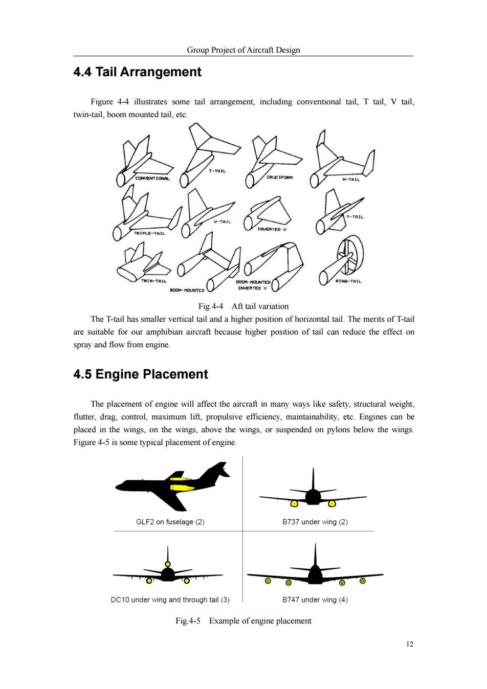
Group Project of Aircraft Design 12 4.4 Tail Arrangement Figure 4-4 illustrates some tail arrangement, including conventional tail, T tail, V tail, twin-tail, boom mounted tail, etc. Fig.4-4 Aft tail variation The T-tail has smaller vertical tail and a higher position of horizontal tail. The merits of T-tail are suitable for our amphibian aircraft because higher position of tail can reduce the effect on spray and flow from engine. 4.5 Engine Placement The placement of engine will affect the aircraft in many ways like safety, structural weight, flutter, drag, control, maximum lift, propulsive efficiency, maintainability, etc. Engines can be placed in the wings, on the wings, above the wings, or suspended on pylons below the wings. Figure 4-5 is some typical placement of engine. Fig.4-5 Example of engine placement
Group Project of Aircraft Design In order to decrease the effect of spray,the engines are decided to be placed above the wings. This placement can not only keep engines away from the water surface to get a clearer takeoff and landing,but also can make takeoff and landing distance shorter. 4.6 Landing Gear Layout In order to coordinate with our fuselage design,the initial landing gear layout is four landing gears.figure 4-6 illustrates the layout. Fig.4-6 Four landing gear The four landing gear design has some advantages.More wheels means less pressure to each wheel.Also the placement of landing gear can be retracted into the hulls which can greatly shorten the length of landing gear to increase its strength.Besides,the arrangement is stable when taking off and touching down.The detailed parameters of landing gear will be discussed in Chapter 11. 4.7 Initial Overall Layout After determining the initial section and their arrangement,the general shape of our aircraft can be seen in the following figure.It should be made clear that the two hulls are not drawn in the figure
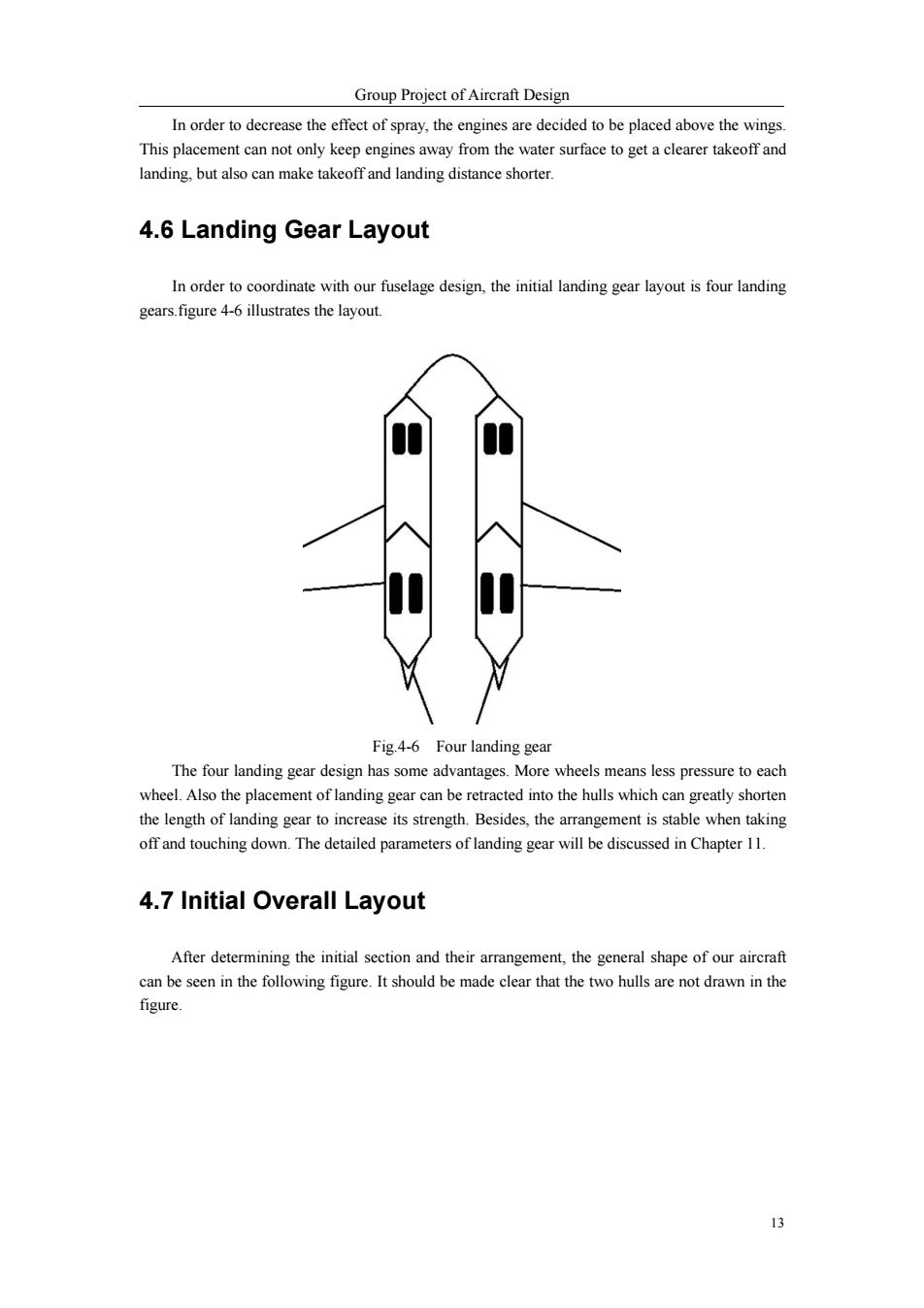
Group Project of Aircraft Design 13 In order to decrease the effect of spray, the engines are decided to be placed above the wings. This placement can not only keep engines away from the water surface to get a clearer takeoff and landing, but also can make takeoff and landing distance shorter. 4.6 Landing Gear Layout In order to coordinate with our fuselage design, the initial landing gear layout is four landing gears.figure 4-6 illustrates the layout. Fig.4-6 Four landing gear The four landing gear design has some advantages. More wheels means less pressure to each wheel. Also the placement of landing gear can be retracted into the hulls which can greatly shorten the length of landing gear to increase its strength. Besides, the arrangement is stable when taking off and touching down. The detailed parameters of landing gear will be discussed in Chapter 11. 4.7 Initial Overall Layout After determining the initial section and their arrangement, the general shape of our aircraft can be seen in the following figure. It should be made clear that the two hulls are not drawn in the figure
Group Project of Aircraft Design Fig.4-7 Initial airplane model 5 Preliminary Weight Estimation 5.1 Introduction The composition of weight includes the empty weight of aircraft,payload,crew weight and fuel weight.The maximum takeoff weight has a relationship with others as the following equation. WTO =Wom +WF+WPL+WE Then we get, Wo=一 Weree +Wp 1-形形 WTo WTo For our transport aircraft,the expected payload is 20ton. WpL 20ton 20000kg Meanwhile,the crew include two pilots,one navigator,and two engineerings.The weight of per staff is about 100kg,containing their equipment. Hence, Werew =5 *100kg=500kg
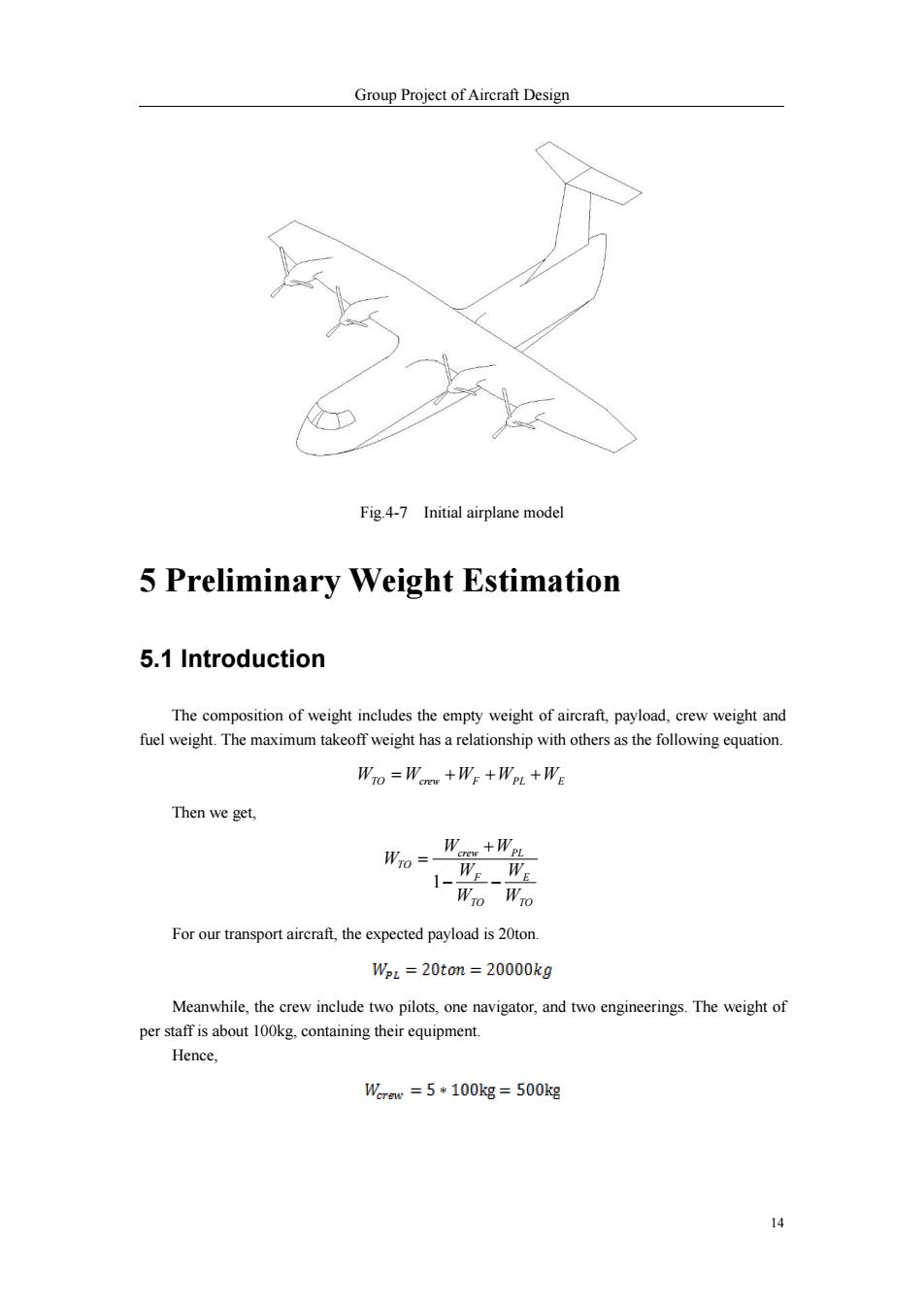
Group Project of Aircraft Design 14 Fig.4-7 Initial airplane model 5 Preliminary Weight Estimation 5.1 Introduction The composition of weight includes the empty weight of aircraft, payload, crew weight and fuel weight. The maximum takeoff weight has a relationship with others as the following equation. WTO Wcrew WF WPL WE Then we get, TO E TO F crew PL TO W W W W W W W 1 For our transport aircraft, the expected payload is 20ton. Meanwhile, the crew include two pilots, one navigator, and two engineerings. The weight of per staff is about 100kg, containing their equipment. Hence

Group Project of Aircraft Design 5.2 Empty-weight Estimation The empty weight fraction can be estimated statistically from historical trends.which are shown below,where generally,flying boats are heavy because they need to carry extra weight for what amounts to a boat hull.From Raymer,we choose the fitting equation parameters between flying boat and military transport. FLYING ,7 SA eUIL E -METAL/WOOD SAILPLANE-UNF RED HO ED IN TURBOPROP ILT-COM AGRICUL TURAL .5 JET RANSPORT /BOMBER 100 1,000 10,000 100,000 1,000,000 TAKEOFF GROSS MEIGHT Fig.5-1 Empty weight to takeoff gross height Here,according to Raymer,statistical curve-fit equations for our amphibious transpot is =1.05Wo006 Wro 5.3 Fuel Estimation The fuel is composed of the used fuel in flight and reserve fuel in the fuel tank WE =WEed +WF.es The chart below describe the fuel consumption condition,that is for the used fuel. Stage,i Description W/w-, W/W-, Refence Set 1 Engine start and warm-up 0.99-0.998 0.996 3 Taxi 0.99-0.998 0.996 3 Take-off 0.99-0.998 0.996 4 Climb to cruise altitude 0.98-0.995 0.99 15
Group Project of Aircraft Design 15 5.2 Empty-weight Estimation The empty weight fraction can be estimated statistically from historical trends. which are shown below, where generally, flying boats are heavy because they need to carry extra weight for what amounts to a boat hull. From Raymer, we choose the fitting equation parameters between flying boat and military transport. Fig.5-1 Empty weight to takeoff gross height Here, according to Raymer, statistical curve-fit equations for our amphibious transpot is . 5.3 Fuel Estimation The fuel is composed of the used fuel in flight and reserve fuel in the fuel tank. WF WF,used WF,res The chart below describe the fuel consumption condition, that is for the used fuel. Stage,i Description , Refence , Set 1 Engine start and warm-up 0.99~0.998 0.996 2 Taxi 0.99~0.998 0.996 3 Take-off 0.99~0.998 0.996 4 Climb to cruise altitude 0.98~0.995 0.99
Group Project of Aircraft Design 5 Cruise to full range 0.863-0.99 (0.769) 6 Loiter 0.99-0.995 (0.995) 1 Descent 0.9850.995 0.99 Landing.taxi,and power 8 0.99-0.998 0.996 off Table.5-1 Fuel consumption in the flight Here cruise is the main fuel-consumption segment,so cruise-segment mission weight fractions should be calculated more exactly.According to Breguet equation, R、 V LInW SFC D W Where cruise SFC of turboprop is sc=w,=05(2a) =0.6731b/hr/b However,obviously it is too large,due to the development of turboprop and referring to the current turboprop SFC data,here we decide to substract 0.1 from the calculation.Hence,cruise SFC=0.57/hr Raymer finds that(L/D)max for a chosen type of airplane depends on the wetted aspect ratio (Awet)defined as: Awat=bwet,where b=wingspan,Swe is the wetted area of the airplane. 747 DUCHES CEBSNA SKYLANE AVRO VULCAN INCLUDINB CANARD AREA Fig.5-2 Wetted area of different aircrafts
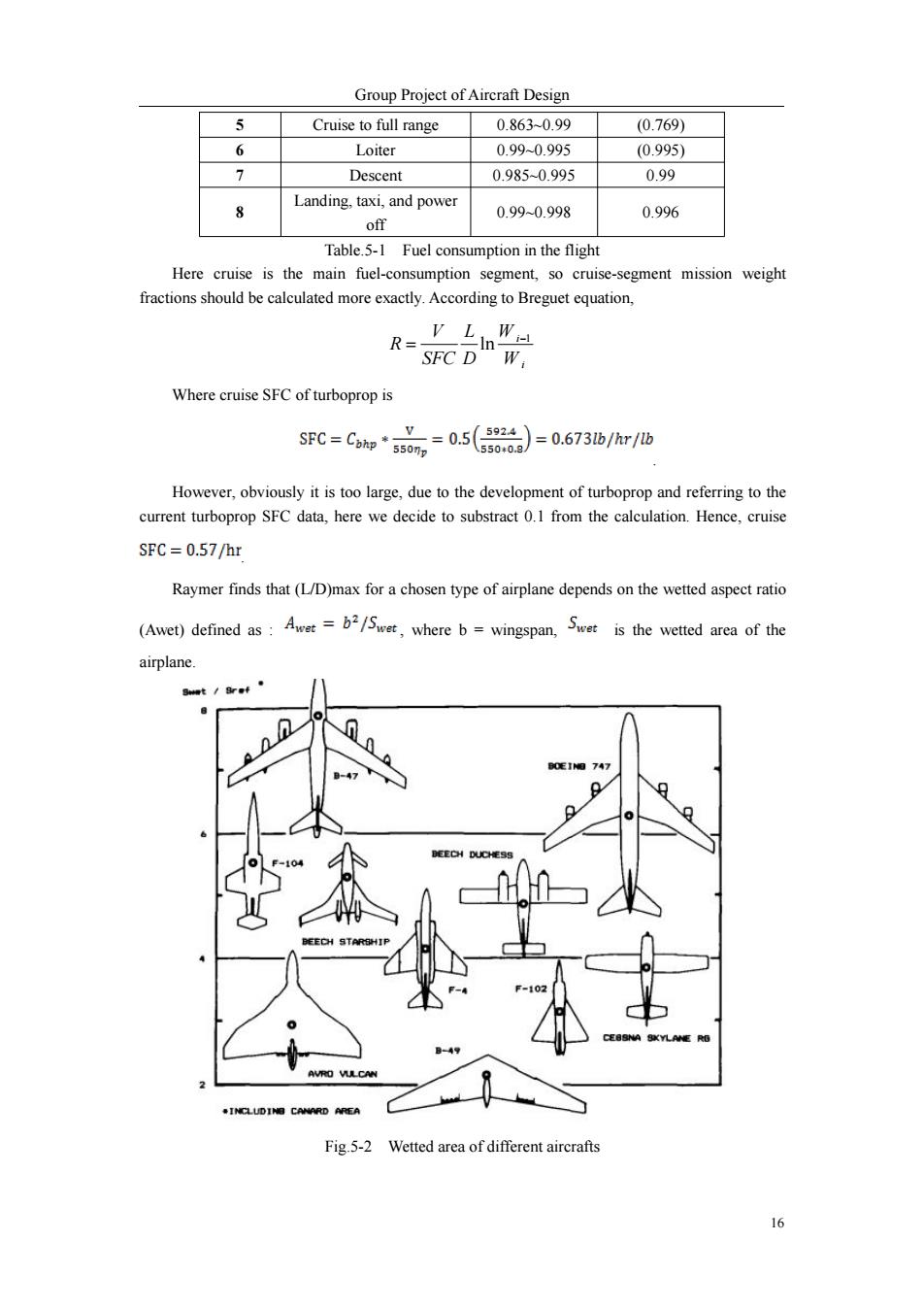
Group Project of Aircraft Design 16 5 Cruise to full range 0.863~0.99 (0.769) 6 Loiter 0.99~0.995 (0.995) 7 Descent 0.985~0.995 0.99 8 Landing, taxi, and power off 0.99~0.998 0.996 Table.5-1 Fuel consumption in the flight Here cruise is the main fuel-consumption segment, so cruise-segment mission weight fractions should be calculated more exactly. According to Breguet equation, i i W W D L SFC V R 1 ln Where cruise SFC of turboprop is . However, obviously it is too large, due to the development of turboprop and referring to the current turboprop SFC data, here we decide to substract 0.1 from the calculation. Hence, cruise . Raymer finds that (L/D)max for a chosen type of airplane depends on the wetted aspect ratio (Awet) defined as : , where b = wingspan, is the wetted area of the airplane. Fig.5-2 Wetted area of different aircrafts