1:6 Y.Yin et al. the 2D gesture contour is discriminative and can be used for character recognition,it is consistent with people's cognition habits for handwriting letters.However,in 3D space,even in a predefined coordinate system,we can look at the 3D contour from different viewing angles,thus the observed 3D contour can be quite different.As shown in Fig.3,when we look at the 3D contour of't'from left to right,the shape and orientation of the character contour change a lot,as the contour located in the red circle in Fig.3(a),Fig.3(b)and Fig. 3(c).For a character,its contour is consisted of one or several strokes in a sequential order and right orientation.If the character contour changes,it can lead to the misrecognition of characters.For example,when we look at the contours of 'b'and 'q'from different viewing angles,we may get similar contours of them and be difficult to distinguish them.Therefore, it is expected to select a proper viewing angle to mitigate the confusion about character contours. 0.2 0.2 02 N 0.2 -0.2 -0.2 0.2 0.2 0202 0.2 2m 份0202 0202 x(m) 0202x8m) (a)From left (b)From center (c)From right Fig.3.Observed 3D contours from different viewing angles 3.2.2 Writing Directions.From a uniform view,2D contours of a same character are similar, while the 3D contours can be quite different,due to the uncertain writing directions.On a 2D plane,the contours of the same character keep the essential shape feature.Even if the orientation of a 2D contour changes,e.g.,the 2D contour rotates in the plane,it still keeps the shape feature of the contour.However,in 3D space,even if we look at the contours of the same character from the same viewing angle,the observed contours can be quite different, as the contours in the red circles shown in Fig.4.This is because the user can write in-air gestures towards different directions.Intuitively,if we can adaptively project the 3D contour into a corresponding coordinate plane (e.g.,Th-Zh plane,yh-Zh plane,or Th-yh plane), we may mitigate the contour distortion caused by writing directions. 0.2 02 0.2 0.2 -02 0.2 0.2 0.2 0.2 0.2 0.2 0.2 -0.2-0.2 x(m -0.2 -0.2 (m) 020.2x9m (a)Writing towardsx plane (b)Writing towards ya plane (c)Writing towardsx-y plane Fig.4.Different contours from the same viewing angle ACM Trans.Sensor Netw.,Vol.1,No.1,Article 1.Publication date:January 2019
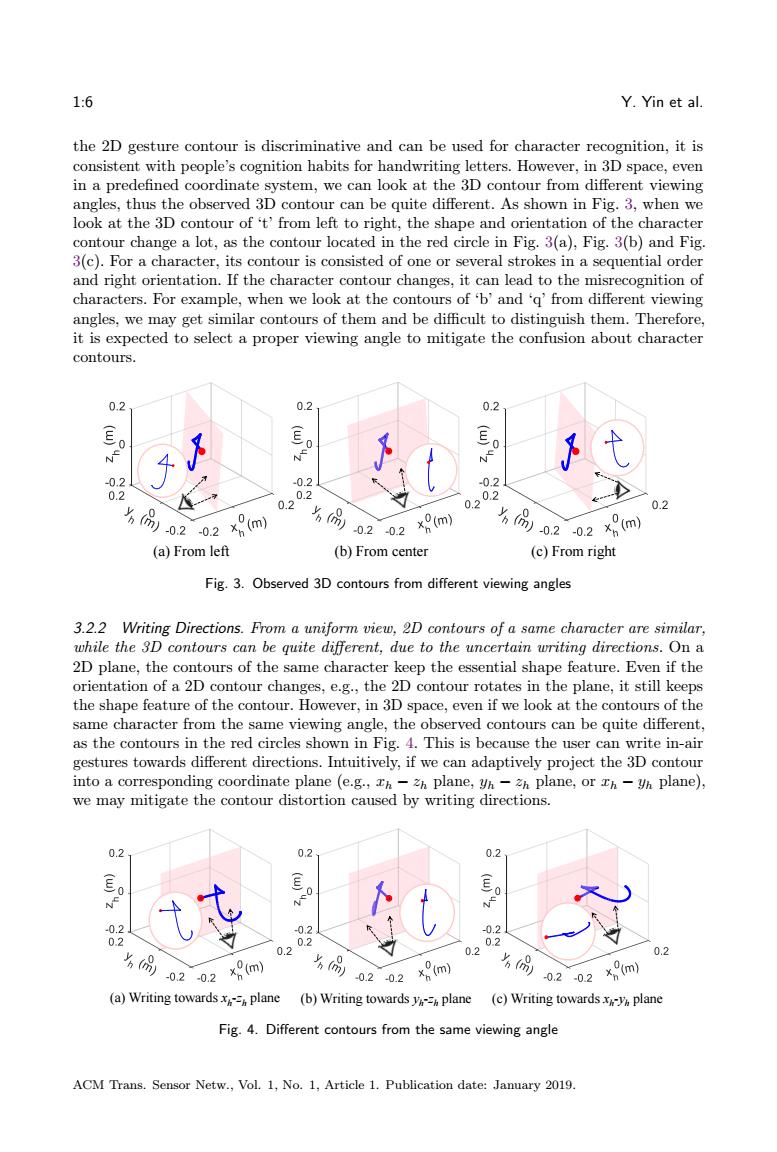
1:6 Y. Yin et al. the 2D gesture contour is discriminative and can be used for character recognition, it is consistent with people’s cognition habits for handwriting letters. However, in 3D space, even in a predefined coordinate system, we can look at the 3D contour from different viewing angles, thus the observed 3D contour can be quite different. As shown in Fig. 3, when we look at the 3D contour of ‘t’ from left to right, the shape and orientation of the character contour change a lot, as the contour located in the red circle in Fig. 3(a), Fig. 3(b) and Fig. 3(c). For a character, its contour is consisted of one or several strokes in a sequential order and right orientation. If the character contour changes, it can lead to the misrecognition of characters. For example, when we look at the contours of ‘b’ and ‘q’ from different viewing angles, we may get similar contours of them and be difficult to distinguish them. Therefore, it is expected to select a proper viewing angle to mitigate the confusion about character contours. (a) From left (b) From center (c) From right Fig. 3. Observed 3D contours from different viewing angles 3.2.2 Writing Directions. From a uniform view, 2D contours of a same character are similar, while the 3D contours can be quite different, due to the uncertain writing directions. On a 2D plane, the contours of the same character keep the essential shape feature. Even if the orientation of a 2D contour changes, e.g., the 2D contour rotates in the plane, it still keeps the shape feature of the contour. However, in 3D space, even if we look at the contours of the same character from the same viewing angle, the observed contours can be quite different, as the contours in the red circles shown in Fig. 4. This is because the user can write in-air gestures towards different directions. Intuitively, if we can adaptively project the 3D contour into a corresponding coordinate plane (e.g., 𝑥ℎ − 𝑧ℎ plane, 𝑦ℎ − 𝑧ℎ plane, or 𝑥ℎ − 𝑦ℎ plane), we may mitigate the contour distortion caused by writing directions. (a) Writing towards xh -zh plane (c) Writing towards xh -y (b) Writing towards y h plane h -zh plane Fig. 4. Different contours from the same viewing angle ACM Trans. Sensor Netw., Vol. 1, No. 1, Article 1. Publication date: January 2019
AirContour 1:7 3.2.3 Contour Distribution.A 2D contour locates in a plane,while a 3D contour can distribute across different planes.In Fig.5(a),we show the human coordinate system (human-frame for short)ch-yh-zh.When the user writes in the air,her/his hand can move left and right,up and down,thus the in-air gesture generates a 3D contour across different planes.At this time,the in-air contour may be mainly located in or close to the plane A3B3C3D3 while not be parallel to any coordinate plane,and we cannot directly project the in-air contour into a coordinate plane for dimensionality reduction,e.g.,Th-Zh plane.As shown in Fig. 5(b),the 3D contour of 'k'distributes across different planes,and the 3D contour is mainly located in or close to the red plane,instead of any coordinate plane (e.g.,the blue plane in Fig.5(a)).Here,the red plane is called principal plane or writing plane,which contains or is close to most of points in the 3D contour,i.e.,the projected contour in the principal plane keeps the essential feature of the 3D contour.Therefore,we are expected to adaptively project the 3D contour into the principal plane,and obtain the essential contour feature of the handwritten character,as the contour 'k'shown in the red circle in Fig.5(b). 0 Plane B Human- B frame -02 C 0.1 0.1 C 8m)0.10.1 (m) (a)Hand movements (b)3D contour across different planes Fig.5.In-air gesture across different planes 3.3 Some Definitions about In-air Gestures According to Section 3.2,the improper viewing angle will lead to the distortion of the observed gesture contour.To mitigate the confusion or misrecognition of gesture contours caused by viewing angles,we first define the appropriate range of viewing angles,based on people's writing habits,i.e.,when the user writes in the air,her/his eyes track the movement of the hand naturally. As shown in Fig.6(a),when the user writes with the left hand,she/he tends to write in front,left side or below,the corresponding viewing angle comes from behind,right side or upside.Accordingly,we select a reference coordinate plane for each viewing angle,i.e., Th-Zh plane,yh-zh plane,and Th-yh plane,respectively.Similarly,as shown in Fig.6(b), when the user writes with the right hand in front,right side or below,the corresponding viewing angle comes from behind,left side or upside.The selected reference coordinate plane under the viewing angles are xh-zh plane,(-yh)-zh plane,and Ih-yh plane, respectively.Therefore,there is a mapping relationship between a reference coordinate plane and a viewing angle.With the selected reference coordinate plane,the user will not view a character contour in the right orientation as a reversed contour(referring to Fig.3(a)and Fig.3(c)).It is worth mentioning that the selected reference coordinate plane is used to indicate the possible orientation of the projected contour in principal plane,as described in Section 4.2.It does not mean that the user can only writes on Th-zh,yh-Zh or y-Zh planes.In fact,the user can write towards arbitrary directions in 3D space. ACM Trans.Sensor Netw.,Vol.1,No.1,Article 1.Publication date:January 2019
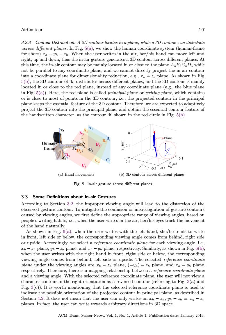
AirContour 1:7 3.2.3 Contour Distribution. A 2D contour locates in a plane, while a 3D contour can distribute across different planes. In Fig. 5(a), we show the human coordinate system (human-frame for short) 𝑥ℎ − 𝑦ℎ − 𝑧ℎ. When the user writes in the air, her/his hand can move left and right, up and down, thus the in-air gesture generates a 3D contour across different planes. At this time, the in-air contour may be mainly located in or close to the plane 𝐴3𝐵3𝐶3𝐷3 while not be parallel to any coordinate plane, and we cannot directly project the in-air contour into a coordinate plane for dimensionality reduction, e.g., 𝑥ℎ − 𝑧ℎ plane. As shown in Fig. 5(b), the 3D contour of ‘k’ distributes across different planes, and the 3D contour is mainly located in or close to the red plane, instead of any coordinate plane (e.g., the blue plane in Fig. 5(a)). Here, the red plane is called principal plane or writing plane, which contains or is close to most of points in the 3D contour, i.e., the projected contour in the principal plane keeps the essential feature of the 3D contour. Therefore, we are expected to adaptively project the 3D contour into the principal plane, and obtain the essential contour feature of the handwritten character, as the contour ‘k’ shown in the red circle in Fig. 5(b). (a) Hand movements Plane (b) 3D contour across different planes Fig. 5. In-air gesture across different planes 3.3 Some Definitions about In-air Gestures According to Section 3.2, the improper viewing angle will lead to the distortion of the observed gesture contour. To mitigate the confusion or misrecognition of gesture contours caused by viewing angles, we first define the appropriate range of viewing angles, based on people’s writing habits, i.e., when the user writes in the air, her/his eyes track the movement of the hand naturally. As shown in Fig. 6(a), when the user writes with the left hand, she/he tends to write in front, left side or below, the corresponding viewing angle comes from behind, right side or upside. Accordingly, we select a reference coordinate plane for each viewing angle, i.e., 𝑥ℎ −𝑧ℎ plane, 𝑦ℎ −𝑧ℎ plane, and 𝑥ℎ −𝑦ℎ plane, respectively. Similarly, as shown in Fig. 6(b), when the user writes with the right hand in front, right side or below, the corresponding viewing angle comes from behind, left side or upside. The selected reference coordinate plane under the viewing angles are 𝑥ℎ − 𝑧ℎ plane, (−𝑦ℎ) − 𝑧ℎ plane, and 𝑥ℎ − 𝑦ℎ plane, respectively. Therefore, there is a mapping relationship between a reference coordinate plane and a viewing angle. With the selected reference coordinate plane, the user will not view a character contour in the right orientation as a reversed contour (referring to Fig. 3(a) and Fig. 3(c)). It is worth mentioning that the selected reference coordinate plane is used to indicate the possible orientation of the projected contour in principal plane, as described in Section 4.2. It does not mean that the user can only writes on 𝑥ℎ − 𝑧ℎ, 𝑦ℎ − 𝑧ℎ or 𝑥𝑦 − 𝑧ℎ planes. In fact, the user can write towards arbitrary directions in 3D space. ACM Trans. Sensor Netw., Vol. 1, No. 1, Article 1. Publication date: January 2019
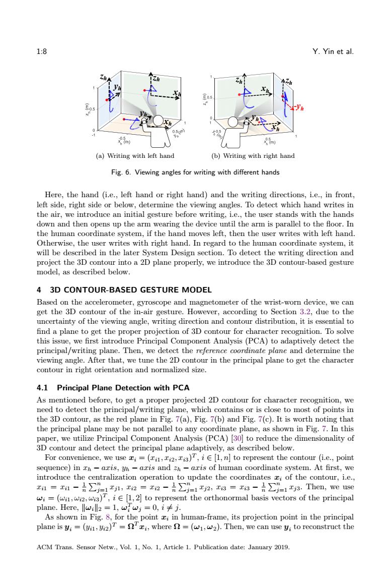
1:8 Y.Yin et al. 0 m m (a)Writing with left hand (b)Writing with right hand Fig.6.Viewing angles for writing with different hands Here,the hand (i.e.,left hand or right hand)and the writing directions,i.e.,in front, left side,right side or below,determine the viewing angles.To detect which hand writes in the air,we introduce an initial gesture before writing,i.e.,the user stands with the hands down and then opens up the arm wearing the device until the arm is parallel to the floor.In the human coordinate system,if the hand moves left,then the user writes with left hand. Otherwise,the user writes with right hand.In regard to the human coordinate system,it will be described in the later System Design section.To detect the writing direction and project the 3D contour into a 2D plane properly,we introduce the 3D contour-based gesture model,as described below. 4 3D CONTOUR-BASED GESTURE MODEL Based on the accelerometer,gyroscope and magnetometer of the wrist-worn device,we can get the 3D contour of the in-air gesture.However,according to Section 3.2,due to the uncertainty of the viewing angle,writing direction and contour distribution,it is essential to find a plane to get the proper projection of 3D contour for character recognition.To solve this issue,we first introduce Principal Component Analysis(PCA)to adaptively detect the principal/writing plane.Then,we detect the reference coordinate plane and determine the viewing angle.After that,we tune the 2D contour in the principal plane to get the character contour in right orientation and normalized size. 4.1 Principal Plane Detection with PCA As mentioned before,to get a proper projected 2D contour for character recognition,we need to detect the principal/writing plane,which contains or is close to most of points in the 3D contour,as the red plane in Fig.7(a),Fig.7(b)and Fig.7(c).It is worth noting that the principal plane may be not parallel to any coordinate plane,as shown in Fig.7.In this paper,we utilize Principal Component Analysis(PCA)[30]to reduce the dimensionality of 3D contour and detect the principal plane adaptively,as described below. For convenience,we usei=(,,)T,i[1,n]to represent the contour (i.e.,point sequence)in Th-aris,yh-axis and zh-aris of human coordinate system.At first,we introduce the centralization operation to update the coordinates i of the contour,i.e., 1=x1-是∑=1,2=2-是∑-12,3=x8-是∑=1a.Then,euse wi=(wi,wi2,wis),iE[1,2]to represent the orthonormal basis vectors of the principal plane.Here,lwill2 =1,wwj=0,ij. As shown in Fig.8,for the point ci in human-frame,its projection point in the principal plane is y;=(vi,)T=i,where =(w1,w2).Then,we can use y;to reconstruct the ACM Trans.Sensor Netw.,Vol.1,No.1,Article 1.Publication date:January 2019
1:8 Y. Yin et al. -yh zh xh zh xh yh zh xh yh zh xh yh (a) Writing with left hand -yh zh xh zh xh yh zh xh yh zh xh zh (b) Writing with right hand Fig. 6. Viewing angles for writing with different hands Here, the hand (i.e., left hand or right hand) and the writing directions, i.e., in front, left side, right side or below, determine the viewing angles. To detect which hand writes in the air, we introduce an initial gesture before writing, i.e., the user stands with the hands down and then opens up the arm wearing the device until the arm is parallel to the floor. In the human coordinate system, if the hand moves left, then the user writes with left hand. Otherwise, the user writes with right hand. In regard to the human coordinate system, it will be described in the later System Design section. To detect the writing direction and project the 3D contour into a 2D plane properly, we introduce the 3D contour-based gesture model, as described below. 4 3D CONTOUR-BASED GESTURE MODEL Based on the accelerometer, gyroscope and magnetometer of the wrist-worn device, we can get the 3D contour of the in-air gesture. However, according to Section 3.2, due to the uncertainty of the viewing angle, writing direction and contour distribution, it is essential to find a plane to get the proper projection of 3D contour for character recognition. To solve this issue, we first introduce Principal Component Analysis (PCA) to adaptively detect the principal/writing plane. Then, we detect the reference coordinate plane and determine the viewing angle. After that, we tune the 2D contour in the principal plane to get the character contour in right orientation and normalized size. 4.1 Principal Plane Detection with PCA As mentioned before, to get a proper projected 2D contour for character recognition, we need to detect the principal/writing plane, which contains or is close to most of points in the 3D contour, as the red plane in Fig. 7(a), Fig. 7(b) and Fig. 7(c). It is worth noting that the principal plane may be not parallel to any coordinate plane, as shown in Fig. 7. In this paper, we utilize Principal Component Analysis (PCA) [30] to reduce the dimensionality of 3D contour and detect the principal plane adaptively, as described below. For convenience, we use 𝑥𝑖 = (𝑥𝑖1, 𝑥𝑖2, 𝑥𝑖3) 𝑇 , 𝑖 ∈ [1, 𝑛] to represent the contour (i.e., point sequence) in 𝑥ℎ − 𝑎𝑥𝑖𝑠, 𝑦ℎ − 𝑎𝑥𝑖𝑠 and 𝑧ℎ − 𝑎𝑥𝑖𝑠 of human coordinate system. At first, we introduce the centralization operation to update the coordinates 𝑥𝑖 of the contour, i.e., 𝑥𝑖1 = 𝑥𝑖1 − 1 𝑛 ∑︀𝑛 𝑗=1 𝑥𝑗1, 𝑥𝑖2 = 𝑥𝑖2 − 1 𝑛 ∑︀𝑛 𝑗=1 𝑥𝑗2, 𝑥𝑖3 = 𝑥𝑖3 − 1 𝑛 ∑︀𝑛 𝑗=1 𝑥𝑗3. Then, we use 𝜔𝑖 = (𝜔𝑖1, 𝜔𝑖2, 𝜔𝑖3) 𝑇 , 𝑖 ∈ [1, 2] to represent the orthonormal basis vectors of the principal plane. Here, ‖𝜔𝑖‖2 = 1, 𝜔 𝑇 𝑖 𝜔𝑗 = 0, 𝑖 ̸= 𝑗. As shown in Fig. 8, for the point 𝑥𝑖 in human-frame, its projection point in the principal plane is 𝑦𝑖 = (𝑦𝑖1, 𝑦𝑖2) 𝑇 = Ω 𝑇 𝑥𝑖 , where Ω = (𝜔1, 𝜔2). Then, we can use 𝑦𝑖 to reconstruct the ACM Trans. Sensor Netw., Vol. 1, No. 1, Article 1. Publication date: January 2019
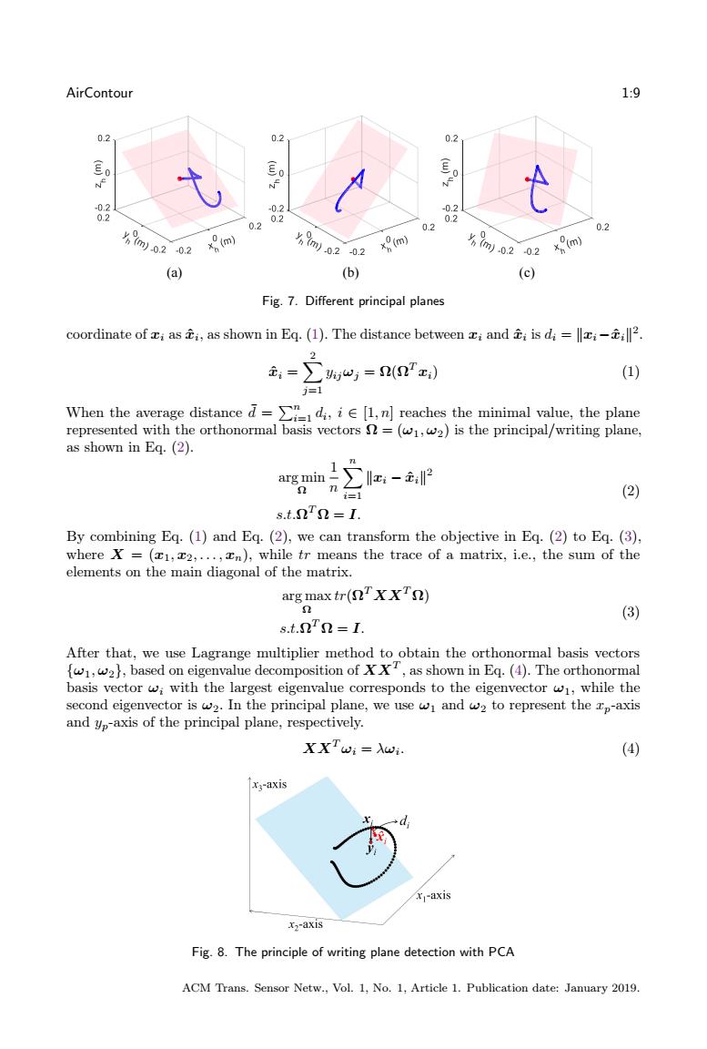
AirContour 1:9 0.2 0.2 0.2 Eo 83 0,2 0.2 83 0.2 02 0.2 m0202 m m)0202 x(m) %}m0202 m (a) (b) (c) Fig.7.Different principal planes coordinate of ci as ti,as shown in Eq.(1).The distance between xi and ti is di=xiil2. ,=∑%=n(n) (1) j=1 When the average distance-∑”_,d,i∈[l,nreaches the minimal value,the plane represented with the orthonormal basis vectors =(w,w2)is the principal/writing plane, as shown in Eq.(2). 11 arg min∑z:-主,2 =1 (2) s.t.nTn=I. By combining Eq.(1)and Eq.(2),we can transform the objective in Eq.(2)to Eq.(3), where X =(x1,x2,...,xn),while tr means the trace of a matrix,i.e.,the sum of the elements on the main diagonal of the matrix. arg max tr(nTXXTn) (3) s.t.nn=I. After that,we use Lagrange multiplier method to obtain the orthonormal basis vectors ,w2,based on eigenvalue decomposition ofT,as shown in Eq.(4).The orthonormal basis vector wi with the largest eigenvalue corresponds to the eigenvector w1,while the second eigenvector is w2.In the principal plane,we use wi and w2 to represent the p-axis and yp-axis of the principal plane,respectively. XXTwi=Xwi. (4) X;-axis x-axis x2-axis Fig.8.The principle of writing plane detection with PCA ACM Trans.Sensor Netw.,Vol.1,No.1,Article 1.Publication date:January 2019
AirContour 1:9 T3, x=55, y=25, [-0.18 0.18] T4, x=40, y=25, z=90, [-0.18 0.18], y取反-Right T5, z=50, y=20, [-0.18 0.18] (a) (b) (c) Fig. 7. Different principal planes coordinate of 𝑥𝑖 as 𝑥^𝑖 , as shown in Eq. (1). The distance between 𝑥𝑖 and 𝑥^𝑖 is 𝑑𝑖 = ‖𝑥𝑖−𝑥^𝑖‖ 2 . 𝑥^𝑖 = ∑︁ 2 𝑗=1 𝑦𝑖𝑗𝜔𝑗 = Ω(Ω 𝑇 𝑥𝑖) (1) When the average distance ¯𝑑 = ∑︀𝑛 𝑖=1 𝑑𝑖 , 𝑖 ∈ [1, 𝑛] reaches the minimal value, the plane represented with the orthonormal basis vectors Ω = (𝜔1, 𝜔2) is the principal/writing plane, as shown in Eq. (2). arg min Ω 1 𝑛 ∑︁𝑛 𝑖=1 ‖𝑥𝑖 − 𝑥^𝑖‖ 2 𝑠.𝑡.Ω 𝑇 Ω = 𝐼. (2) By combining Eq. (1) and Eq. (2), we can transform the objective in Eq. (2) to Eq. (3), where 𝑋 = (𝑥1, 𝑥2, . . . , 𝑥𝑛), while 𝑡𝑟 means the trace of a matrix, i.e., the sum of the elements on the main diagonal of the matrix. arg max Ω 𝑡𝑟(Ω 𝑇 𝑋𝑋𝑇 Ω) 𝑠.𝑡.Ω 𝑇 Ω = 𝐼. (3) After that, we use Lagrange multiplier method to obtain the orthonormal basis vectors {𝜔1, 𝜔2}, based on eigenvalue decomposition of 𝑋𝑋𝑇 , as shown in Eq. (4). The orthonormal basis vector 𝜔𝑖 with the largest eigenvalue corresponds to the eigenvector 𝜔1, while the second eigenvector is 𝜔2. In the principal plane, we use 𝜔1 and 𝜔2 to represent the 𝑥𝑝-axis and 𝑦𝑝-axis of the principal plane, respectively. 𝑋𝑋𝑇 𝜔𝑖 = 𝜆𝜔𝑖 . (4) Fig. 8. The principle of writing plane detection with PCA ACM Trans. Sensor Netw., Vol. 1, No. 1, Article 1. Publication date: January 2019